Connection
6 — German Control Remote - 09.11.2015
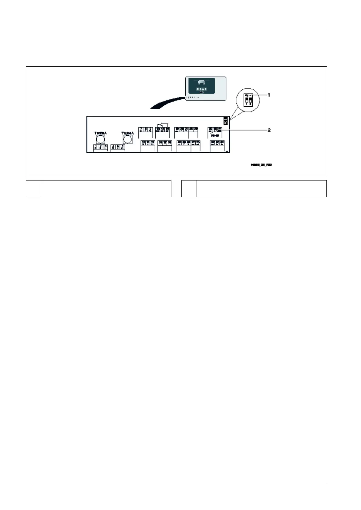
4.2 Connection of the RS-485 connector to the Reflex Control Basic controller
Connection plan of the Reflex Control Basic.
1
DIPswitches1and2inactiveposition
• Theterminatorisactivated
2 ConnectionterminalsforRS‐485connection
Proceedasfollows:
1. OpenthehousingcoveroftheControlBasiccontroller.
2. Installtheadapterinthetoprightareaofthehousingbottom.
3. SecuretheReflexControlRemoteontheadapter.
4. ConnectthemainboardtotheReflexControlRemoteusingthesupplied
RS485cable.
o Connectiontoterminals29,30.
o RJ45jackontheReflexControlRe
mote
5. RouteaLANcable
throughacablepenetrationandconnectittotheReflexControlRemote.
6. Connectthepowersupply.
o Usethesuppliedmainsadapter.
7. ActivatetheterminatorsonthemainboardoftheControlBasic.
o UseDIPswitches1and2.