Settings
8 — German Control Remote - 09.11.2015
5 Settings
Danger – electric shock!
• Risk of serious injury or death due to electric shock. Some parts of the main board may still carry 230 V voltage even
with the device physically isolated from the 230 V power supply.
– Before you remove the covers, completely isolate the device controller from the power supply.
– Verify that the main circuit board is voltage-free.
5.1 Setting the terminators in RS-485 networks
ExamplesfortheactivationanddeactivationofterminatorsinRS–485networks .
DIPswitches1and2arelocatedonthemainboardoftheControlBasic/Touch
MaximumlengthforanRS–485connectionis 1000metres
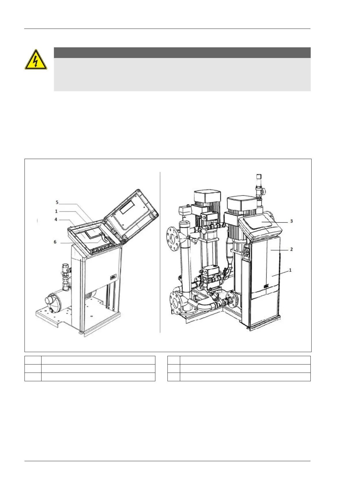
Device controllers with Reflex Control Remote.
Control Basic controller with Reflex Control Remote Control Touch controller with Reflex Control Remote
1 ControlRemotePCB4 ControlBasicmainboard
2 ControlTouchI/OPCB5 RS‐485connection
3 ControlTouchTANPCB6 Voltagesupply
IfonlytheReflexControlRemoteispresentonthecontroller,theterminatorsontheReflexControlTouch/
Basicmustbeswitchedon.Ifextramodulesareadded,theyareconnectedtotheRS485interfaceofthe
ControlTouch/Basic.