58 | Bellavista® B36XTCE-11 Gas Fireplace
installation
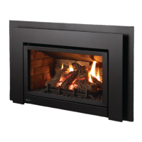
AERATION ADJUSTMENT
The burner aeration is factory set but may need adjusting due to either the local gas supply or altitude. Open the air shutter for a blue flame or close for a
more yellow flame.
Minimum Air Shutter Opening:
NG 1/4"
LP 3/8"
CAUTION: Carbon will be produced if air
shutter is tightly closed.
Note: Any damage due to carboning
resulting from improperly setting
the aeration controls is NOT
covered under warranty.
Air shutter rod - located to the left
of the valve assembly.
CAUTION: Label all wires prior to disconnection
when servicing controls. Wiring errors can cause
improper and dangerous operation.
Caution: Ensure that the wires do not touch any
hot surfaces and are away from sharp edges.
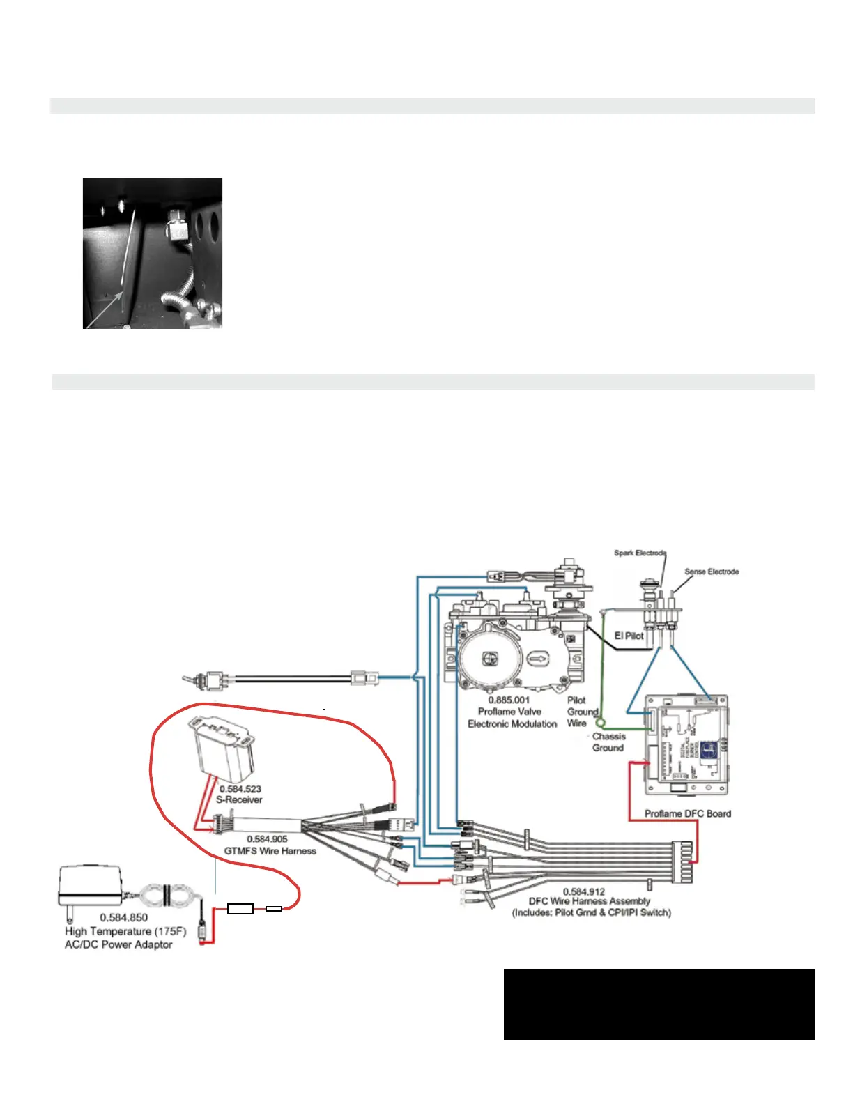
Proflame System
Configuration
886 GTMF
Wire Diagram
SureFire™ Switch
885
AC Adaptor
WIRING DIAGRAM
This heater does not require a 120V A.C. supply for operation but it is highly recommended to install the supplied AC adaptor to eliminate the need for batteries.
In case of a power failure, the burner switch and the optional remote control will continue to operate if batteries are installed in the receiver. However, a 120V
A.C. power supply is needed for the fan/blower operation.
(Do not cut the ground terminal off under any circumstances.)
NOTE: Even if the fan is not purchased with the unit, it is still a good idea to bring power to the receptacle box (provided with the
unit) in case the fan is installed at a later date.
0.584.622