RCF manual Chapter 6 Installation 19
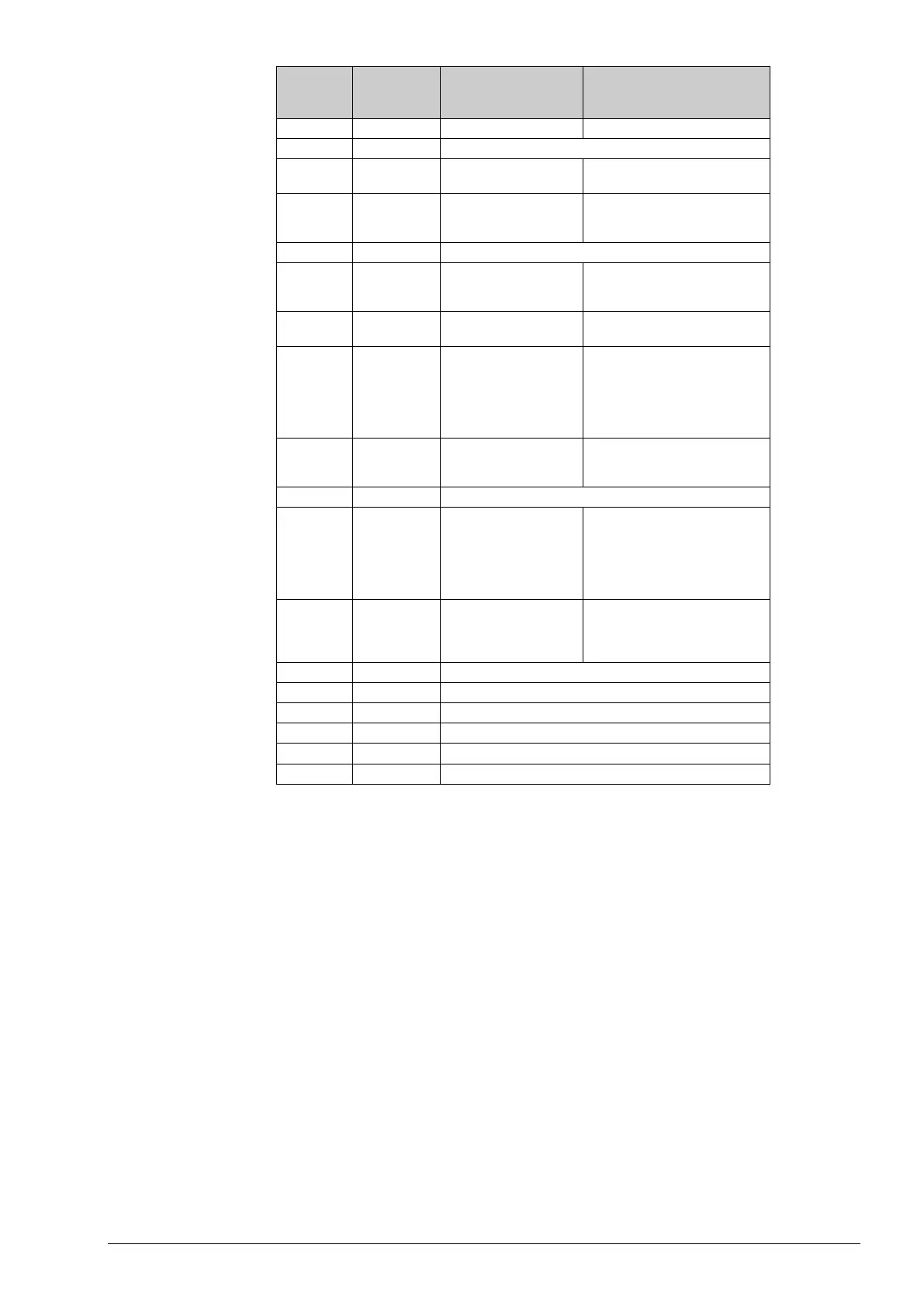
Terminal Designation Description Function
10 L 230 V AC Line Supply voltage
11 NC Not connected
12 N 230 V AC Neutral
Power supply (internally connected
to terminal 13)
13 N Fan-coil common / 230 V
AC Neutral
Common fan-coil connector
(internally connected to terminal
30
Not connected
31 DO4 Digital output 4 for
heating/cooling or opening
with 3-point actuator
Digital output, 230 V AC, max 300
mA (3 A initially)
32 CDO45 Common DO4 & 5 Common connection for digital
33
DO5 Digital output 5 for
cooling or closing with 3-
point actuator.
Heating/cooling signal
when electric heater is
Digital output, 230 V AC, max 300
mA (3 A initially)
40
DI Digital input Floating (potential-free) window
contact or occupancy contact.
Configurable for NO/NC.
41
AGnd
Analogue ground
42 AI Analogue input For external room sensors or
supply air temperature limitation
sensor, PT1000. Measuring range
0...50°C. The sensor is connected
between terminals 42 and 44,
43 UI Universal input Potential-free window contact or
dito change-over input
(configurable for NO/NC) or
analogue PT1000 sensor.
44
AGnd
Analogue ground
50
AGnd
Analogue ground
Wiring of control signal for EC fan
 Loading...