│
12
EGULUS - SRS 3 Controller - www.re
ulus
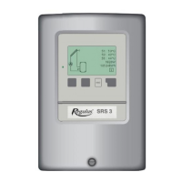
B 9 - Solar system with 2 storage tanks and zone valve
Sensor connection - max. 12V Mains voltage - 230V 50Hz
Low voltage - sensor connection
Terminal: connection for:
S1 (2×) sensor 1 collector
S2 (2×) sensor 2 storage tank 1
S3 (2×) sensor 3 storage tank 2
The polarity of the sensors is freely selectable.
Mains voltage - 230V 50Hz
Terminal: connection for:
L mains phase conductor L
N mains neutral conductor N
R1 pump L (speed)
N pump N
R2 zone valve L
N zone valve N
PE protective conductor (green-yellow)
Note: Actuating direction of zone valve:
R2 off = valve closed = flow direction B-AB = storage tank 1 charging (sensor S2)
R2 on = valve open = flow direction A-AB = storage tank 2 charging (sensor S3)
R1 output: for speed control of standard pumps, minimum load 20VA.
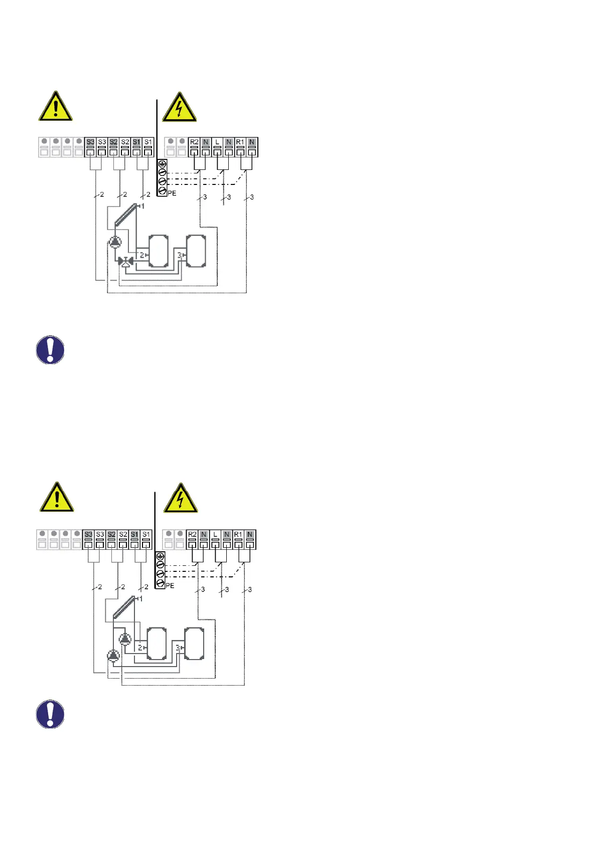
B10 - Solar system with 2 storage tanks and 2 pumps
Sensor connection - max. 12V Mains voltage - 230V 50Hz
Low voltage - sensor connection
Terminal: connection for:
S1 (2×) sensor 1 collector
S2 (2×) sensor 2 storage tank 1
S3 (2×) sensor 3 storage tank 2
The polarity of the sensors is freely selectable.
Mains voltage - 230V 50Hz
Terminal: connection for:
L mains phase conductor L
N mains neutral conductor N
R1 pump (storage tank 1) L
N pump (storage tank 1) N
R2 pump (storage tank 2) L
N pump (storage tank 2) N
PE protective conductor (green-yellow)
R1 output: for speed control of standard pumps, minimum load 20VA.
max. 12V 230VAC
Sensor side
Danger
Danger
Mains side
Mains
230VAC
Optional
Caution
Caution
max. 12V 230VAC
Sensor side
Danger
Danger
Mains side
Mains
230VAC
Optional
B
AB
A