│
8
EGULUS - SRS 3 Controller - www.re
ulus
B - ELECTRIC WIRING
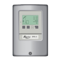
B 1 - Solar system with storage tank
Example: solar system with storage tank and el. heating rod with integrated thermostat.
Sensor connection - max. 12V Mains voltage - 230V 50Hz
Low voltage - sensor connection
Terminal: connection for:
S1 (2×) sensor 1 collector
S2 (2×) sensor 2 storage tank
S3 (2×) sensor 3 (e.g. for heat balance)
The polarity of the sensors is freely selectable.
Mains voltage - 230V 50Hz
Terminal: connection for:
L mains phase conductor L
N mains neutral conductor N
R1 pump L (speed)
N pump N
R2 pump L (no speed control)
R1 pump N
PE protective conductor (green-yellow)
Note: Sensor 3 can be used to measure heat quan-
tity supplied by the solar system.
R1 output: for speed control of standard pumps, minimum load 20VA.
Caution
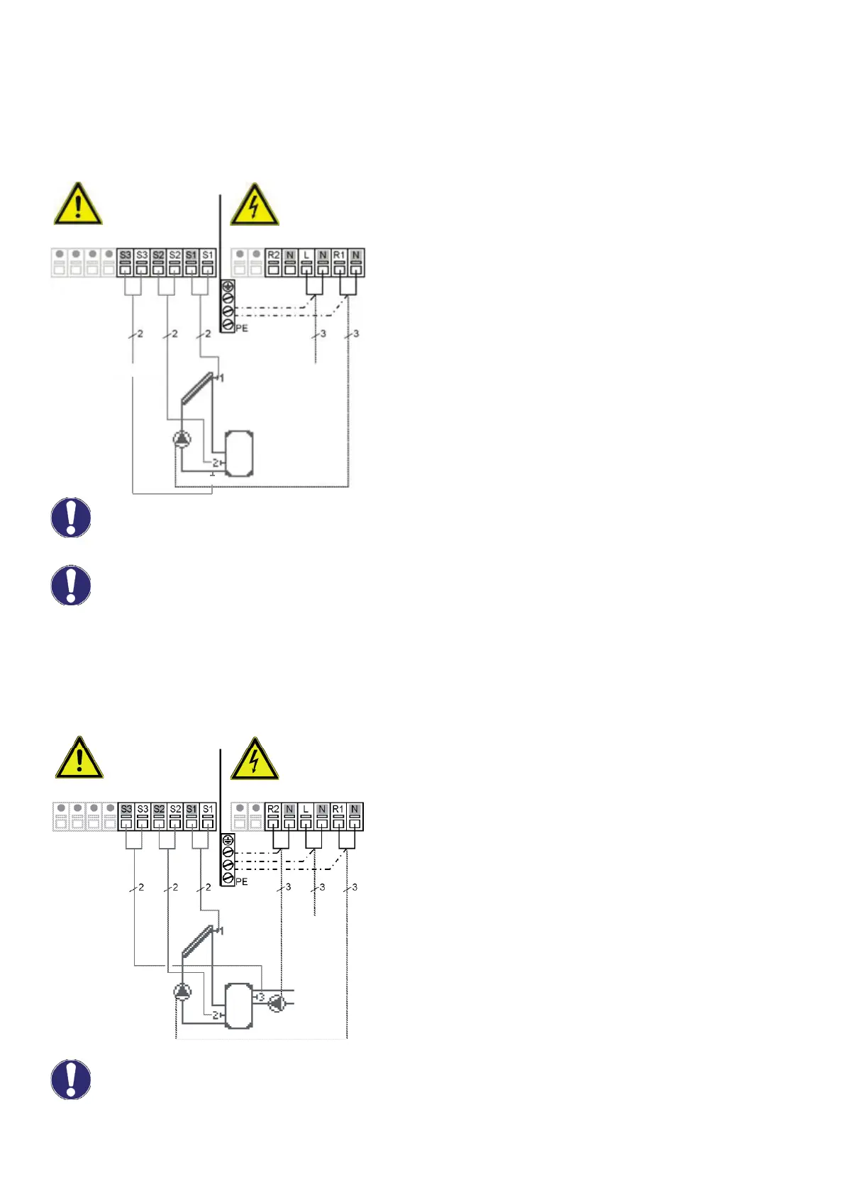
B 2 - Solar system with thermostat for storage tank heating or cooling
Example: solar system with storage tank heated with a gas boiler or el. heating rod, controller regulated.
Sensor connection - max. 12V Mains voltage - 230V 50Hz
Low voltage - sensor connection
Terminal: connection for:
S1 (2×) sensor 1 collector
S2 (2×) sensor 2 storage tank lower
S3 (2×) sensor 3 storage tank upper
The polarity of the sensors is freely selectable.
Mains voltage - 230V 50Hz
Terminal: connection for:
L mains phase conductor L
N mains neutral conductor N
R1 pump L (speed)
N pump N
R2 thermostat function L
N thermostat function N
PE protective conductor (green-yellow)
R1 output: for speed control of standard solar pumps, minimum load 20VA.
max. 12V 230VAC
Sensor side
Danger
Danger
Mains side
Mains
230VAC
Optional
Caution
Danger
Danger
Mains side
Mains
230VAC
Optional
Sensor 3
Sensor side
max. 12V 230VAC
3
Caution
In B1 wiring diagram of Solar system with storage tank, the relays R1 and R2 close together, i.e.
when closed, voltage will appear on R2 terminal as well.