│
14
EGULUS - SRS 3 Controller - www.re
ulus
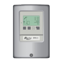
B13 - Solar system with pool and storage tank
Sensor connection - max. 12V Mains voltage - 230V 50Hz
Low voltage - sensor connection
Terminal: connection for:
S1 (2×) sensor 1 collector
S2 (2×) sensor 2 storage tank
S3 (2×) sensor 3 pool
The polarity of the sensors is freely selectable.
Mains voltage - 230V 50Hz
Terminal: connection for:
L mains phase conductor L
N mains neutral conductor N
R1 pump L (speed)
N pump N
R2 pool pump + 3-way valve L
N pool pump + 3-way valve N
PE protective conductor (green-yellow)
Note: Actuating direction of zone valve:
R2 off = valve closed = flow direction B-AB = storage tank charging (sensor S2)
R2 on = valve open = flow direction A-AB = pool heating (sensor S3)
R1 output: for speed control of standard pumps, minimum load 20VA
Caution
max. 12V 230VAC
Sensor side
Danger
Danger
Mains side
Mains
230VAC
Optional
B
AB
A
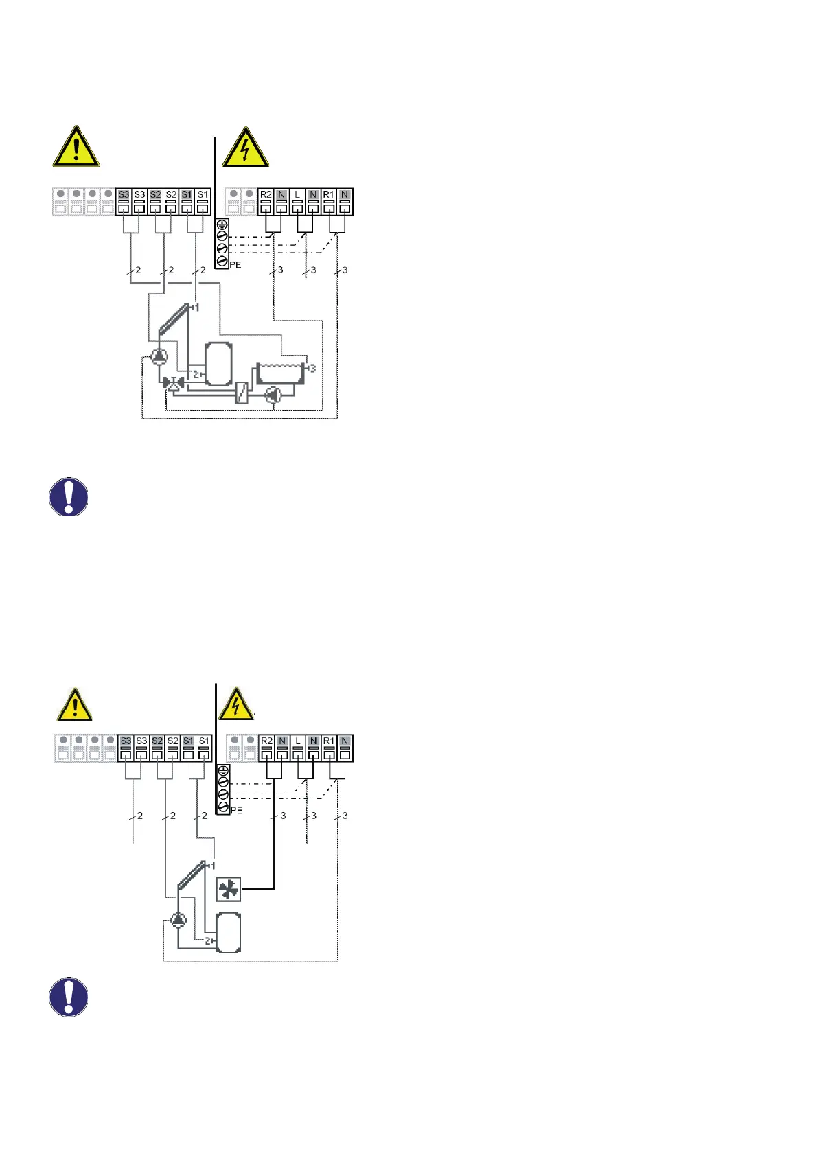
B14 - Solar system + cooling 1
Sensor connection - max 12V Mains voltage - 230V 50Hz
Low voltage - sensor connection
Terminal: connection for:
S1 (2×) sensor 1 collector
S2 (2×) sensor 2 storage tank
S3 (2×) sensor 3
The polarity of the sensors is freely selectable.
Mains voltage - 230V 50Hz
Terminal: connection for:
L mains phase conductor L
N mains neutral conductor N
R1 pump L (speed)
N pump N
R2 cooling L
N cooling N
PE protective conductor (green-yellow)
R1 output: for speed control of standard pumps, minimum load 20VA
Caution
Sensor side
max. 12V
Danger
Mains side
230VAC
Danger
Optional
Sensor 3
Mains
230VAC
Description of cooling function - see chapter D 6.4.1