10
REMKO GPS series
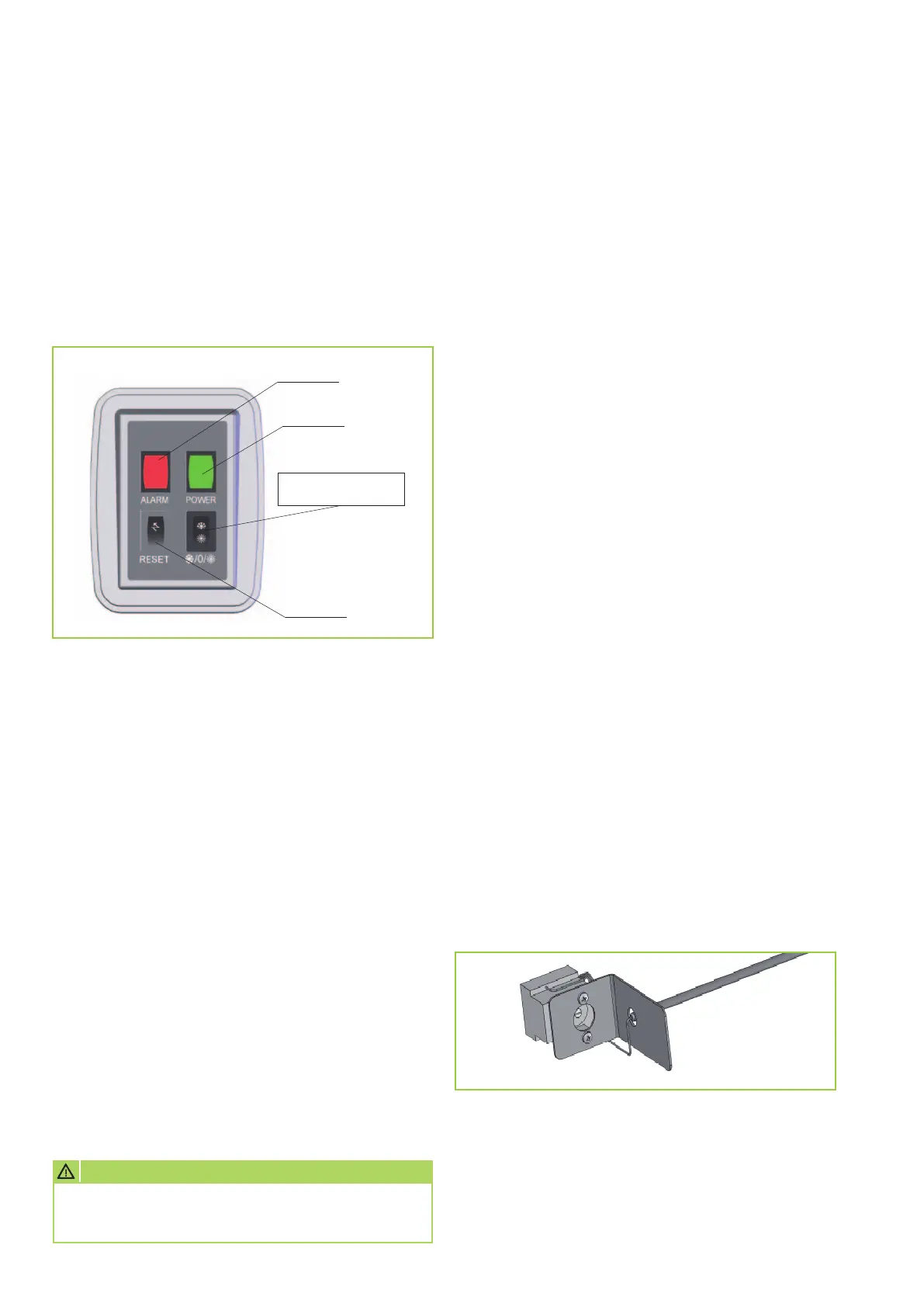
Control panel
The hot air heaters from the GPS series are fitted as
standard with a control panel on the front of the unit.
All unit information or fault indications are displayed
on this control panel.
General notes
Toggle switch
Z Summer / d Winter
Reset key
GREEN LED
RED LED
Safety thermostat
High or low flame
The units are serially equipped with a room
temperature probe NTC1 on the rear side of the unit
so that the intake temperature of the fans is
monitored. The operation of the two stages takes
place depending on the temperature value measured
by the probe compared to the value set inside
the thermostat housing. The thermostat can be
set to the desired temperature value via a screw.
This value should be set a few degrees above
the desired room temperature. If the temperature rises
above the set value then the burner is set at a lower
flame, which reduces the heat output. In this way
the air blown into the room is heated less heavily.
However, the thermostat for controlling the high
or low flame is by no means a replacement for a room
thermostat, which must be installed in all instances.
The optimisation of the temperature value must take
place during operation of the system and depends on
the distance of the fan-assisted air heater to the floor
and the required temperature conditions. The gas wall
heater is normally installed at a distance of 2.5 - 4 m
from the floor.
The GPS unit series is equipped with a safety
thermostat with automatic reset function and positive
safety device as standard. This means that the safety
equipment also triggers with a breakage.
If the thermostat is tripped, the burner is stopped
via the flame monitoring unit and a subsequent
fault shut-down of the flame monitoring unit is
triggered. The thermostat probe is located behind
the top outflow fins, in the centre of the housing.
The fault shut-down is displayed on the control panel
by the red indicator light.
Because this is a safety-relevant error, the fault shut-
down is permanent and requires a manual reset.
The illumination of the green LED means that
the unit is connected to the mains.
The illumination of the red LED indicates
a malfunction of the unit.
Using the malfunction diagnostics, the cause
of the malfunction can be identified by the different
types of flashing signals of the red LED.
Summer/winter toggle switch
Also, a manually-operated toggle switch d / 0 / Z
is installed on the front of the unit, which enables
switching the unit from winter operation d to summer
mode Z (continuous ventilation).
In the central position [0] all unit functions are
switched off.
Reset key
A manually-actuated reset key is installed on the front
of the unit, which enables the unlocking of the unit
after the malfunctions F1, F2, F5, F6 or F8.
CAUTION
Before resetting safety equipment, the cause
of the trigger must be identified and rectified.
 Loading...