11
The desired comfortable temperature should be
reached and maintained with this. However, it is
necessary to ensure that the units are operated with
the lowest necessary temperature value, in order
to maintain these conditions. The thermostat is set
to 20°C in the factory. This value enables a mid-
level installation range between 3 and 5 metres with
room temperatures between 17 and 19°C (see graph
below).
Malfunction diagnostics
With a malfunction, the red alarm light illuminates
constantly on the control panel.
To cancel the malfunction, it is necessary to press
the reset key for longer than 1 second.
If the malfunction is still present after the reset,
please do not attempt a reset more than three times
and contact customer service to arrange a repair.
To activate diagnostics, it is necessary to press
the reset key for longer than 5 seconds. The red
light will start to flash. The error number can now be
determined on the basis of the number of flashing
signals. The flash sequence is repeated and displayed
with a pause of 2 seconds between each repetition.
F1
- LED flashes once quickly
F2
- LED flashes twice quickly
F5
- LED flashes five times quickly
F6
- LED flashes six times quickly
F8
- LED flashes eight times quickly
Types of malfunction
The malfunctions (lock-outs) displayed and saved
by the control board have the following causes:
F1
- Malfunction of the flame monitoring unit
because of unsuccessful ignition of the
burner; the control board arranges for a series
of automatic deactivation attempts prior
to reporting the malfunction.
F2
- Tripping of the safety thermostat.
If the temperature detected by the thermostat
is too high, it disconnects and disables
the operation of the unit.
F5
- Burner fan defective;
Combustion air fan is defective or the signal to
the control board lies beyond the tolerance range
of the desired speed.
F6
- Combustion air fan is defective or the signal
to the control board lies beyond the tolerance
range of the desired speed.
F8
- The control board has identified an undesired
response.
The malfunctions F1 and F2 are caused by safety
devices and therefore are permanent:
The malfunction persists when switching off and
restarting the mains voltage and can only be unlocked
manually.
CAUTION
Before resetting safety equipment, the cause
of the trigger must be identified and rectified.
NOTE
Safety devices may not be bypassed or disabled
during operation of the unit!
NOTE
Set the temperature on the internal thermostat
at least 2 K above the desired room temperature.
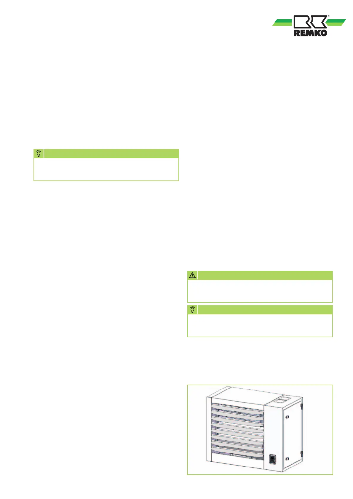
Fin alignment
Before switching the unit on, open the fins at least
45°, in order to avoid overheating the combustion
chamber.
 Loading...