7
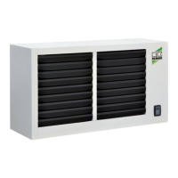
Safety thermostat(s) with vertical air flow
A safety thermostat (STB) is installed on the units
for each fan, for manual resetting.
If the safety thermostats are triggered then a safety
shutdown is also triggered.
The thermostat is installed in the area of the heat
exchanger in order to monitor the temperature
at its output.
The disabling of the unit caused by the triggering
of the safety thermostat is displayed by the error
indicator light on the front of the unit.
Air/gas premix
The units are equipped with a burner with complete
air/gas premix.
This mixing process takes place in the fan
of the burner motor. The air suctioned in by
the fan flows through the Ventura tube, where an
underpressure is created, which draws in the gas.
In the process, a constant air/gas mixture is created.
The ratio of air and gas pressure is 1:1.
This value can be changed through the offset
regulating screw found on the gas valve.
The amount of gas is already adjusted upon delivery
of the units and the screw is sealed.
With the adjusting screw located at the Venturi tube,
a fine adjustment can take place, which regulates
the maximum gas flow rate and thus determines
the carbon dioxide (CO
2
) content of the flue gases
The screw is not sealed in order to enable conversion
of the fan-assisted air heater to another type of gas.
PLEASE NOTE:
For the offset and CO
2
adjustment.
The control board of the units enables the speed
regulation of the burner motor with DC depending
on the heat output required in the space.
By changing the speed the air flow rate and thus
the gas flow rate are changed.
Minimum and maximum speeds of the fan are
two values that cannot be changed.
Fans
The switching on of the fans is time-controlled
by the control board, whereby the timing begins with
the switching-on of the main burner.
The delayed switch-on prevents cold air from being
blown into the room.
Switching off the unit
If there is no longer a heat requirement (room
temperature above the adjusted setpoint value),
the control board switches off the burner.
The burner fan runs for the secondary ventilation
of the combustion chamber for a fixed, pre-set time.
The fan(s) likewise run afterwards on a time-
controlled basis until the heat exchanger is cooled.
If a new heat requirement should take place during
the follow-up phase, the control board will wait for
the fans to switch off and then proceed with a reset
and begin a new cycle.
CAUTION
Before resetting safety equipment, the cause
of the trigger must be identified and rectified.
NOTE
Safety devices may not be bypassed or disabled
during operation of the unit!
IMPORTANT NOTE!
The interruption of the current supply during burning
operation or in the follow-up cooling phase is not
permitted, because lack of a secondary ventilation
of the heat exchanger can lead to significant damage:
■
Overheating of the unit with the resulting
expiration of the guarantee
■
Damage to the fan of the burner and its
components
■
Tripping of the safety thermostat and the
associated lock-out of the safety thermostat (STB).
Therefore no new unit start without manual
resetting
■
Damage to electrical lines
NOTE
The model with vertical air flow must be specified
at the time of order placement, because the probe
is not installed as standard.
 Loading...