RZ/A2M SUB Board RTK79210XXB00000BE 2. Function specifications
R20UT4398EJ0100 Rev.1.00 2-3
2018.10.11
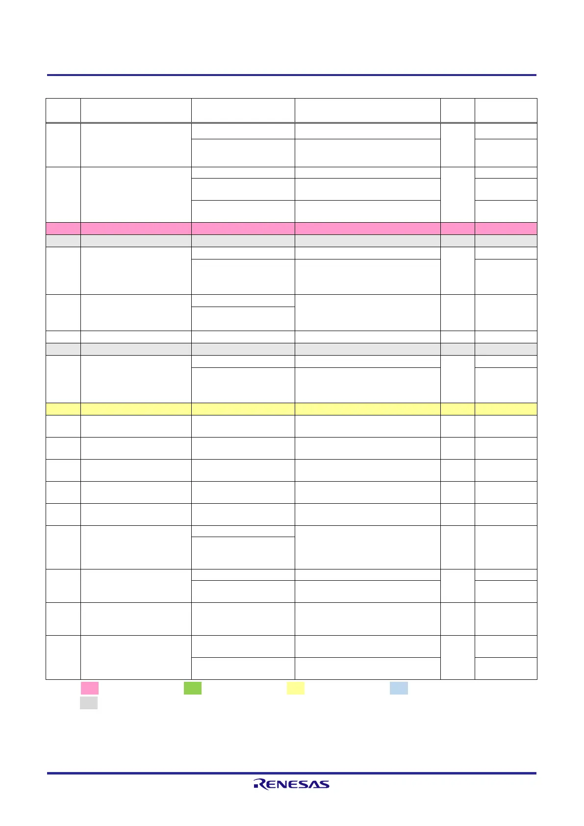
Table 2.2.2 List of RZ/A2M Pin Function Selections Used on the RTK79210XXB00000BE (2)
PE_4 /
ET0_CRS/RMII0_CRSDV /
VIO_D4 / SSIFS0 /
MTIOC0B
Connects to Ethernet PHY1 (U27)
Connects to CMOS camera connector
(CN17)
P9_1 / A9 / DRP15 /
DV0_DATA8 / RxD4 /
SSIFS2
Connects to SDRAM (U3) connection
Connects to DRP connector (CN2)
Connects to USB Micro-B port (CN5)
via USB serial converter IC (U23)
PE_1 /
ET0_RXD0/RMII0_RXD0 /
VIO_D7 / RxD2 / POE8 /
VBUSIN1 / IRQ1
Connects to Ethernet PHY1 (U27)
Connects to CMOS camera connector
(CN17)
PA_4 / A20 / DV0_DATA9 /
LCD0_DATA14 /
SCI_TXD0 / MTIOC0C
Connects to digital image input/output
connector (CN15)
PK_1 /
ET1_TXD0/RMII1_TXD0 /
NAF4 / CC1_RA0 /
CAN_CLK / SSIDATA2
Connects to Ethernet PHY2 (U28)
Connects to NAND flash memory
(U31)
Connects to serial flash memory (U2
on the CPU board)
Connects to serial flash memory (U2
on the CPU board)
Connects to serial flash memory (U2
on the CPU board)
Connects to serial flash memory (U2
on the CPU board)
Connects to serial flash memory (U2
on the CPU board)
PF_5 / TxD2 /
DV0_DATA20 /
LCD0_DATA3 / MTIOC6B /
SSIFS0
Connects to digital image input/output
connector (CN15)
P6_3 /
ET0_TXD1/RMII0_TXD1 /
VIO_HD / TxD3 / POE0
Connects to Ethernet PHY1 (U27)
Connects to CMOS camera connector
(CN17)
PH_0 / AUDIO_CLK /
VIO_D1 / GTIOC4A /
MTIOC1A / CC1_RD0 / IRQ3
Connects to CMOS camera connector
(CN17)
Connects to DIP switch (SW1 on the
CPU board)
Connects to USB CC logic controller
(U7 on the CPU board)
[Note] : 3.3V power source, : 1.8V power source, : 1.2V power source, : 3.3V or 1.8V power source,
: GND
Red text CPU board setting display.
 Loading...


