RZ/A2M SUB Board RTK79210XXB00000BE 2. Function specifications
R20UT4398EJ0100 Rev.1.00 2-13
2018.10.11
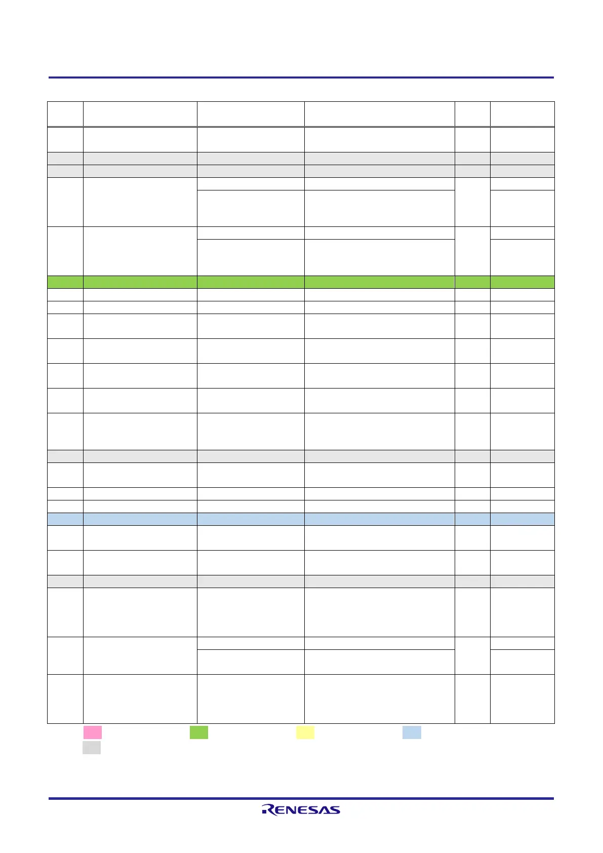
Table 2.2.12 List of RZ/A2M Pin Function Selections Used on the RTK79210XXB00000BE (12)
Connects to microSD card slot (CN1
on the CPU board) connection
PK_4 /
ET1_RXD0/RMII1_RXD0 /
NAF7 / OVRCUR1 /
CAN0TX / MISO0 / IRQ6
Connects to Ethernet PHY2 (U28)
Connects to NAND flash memory
(U31)
P3_1 /
ET1_RXER/RMII1_RXER /
FALE / VBUSEN0 /
CAN1RX / RSPCK2 / IRQ6
Connects to Ethernet PHY2 (U28)
Connects to NAND flash memory
(U31)
Connects to SD card slot (CN10)
Connects to SD card slot (CN10)
Connects to microSD card slot (CN1
on the CPU board)
Connects to microSD card slot (CN1
on the CPU board)
Connects to MIPI CSI-2 connector
(CN2 and J1 on the CPU board)
Connects to MIPI CSI-2 connector
(CN2 and J1 on the CPU board)
PG_4 / ET0_TXER /
VIO_D15 / RSPCK1 /
MTIOC4A / GTIOC1A
Connects to CMOS camera connector
(CN17)
P5_4 / AN004 / IRQ0 /
SD1_CD
Connects to SD card slot (CN10)
Connects to SD card slot (CN10)
Connects to SD card slot (CN10)
Connects to MIPI CSI-2 connector
(CN2 and J1 on the CPU board)
Connects to MIPI CSI-2 connector
(CN2 and J1 on the CPU board)
PG_6 / ET0_RXD2 /
VIO_D13 / MISO1 /
MTIOC4C / GTIOC2A /
IRQ5
Connects to CMOS camera connector
(CN17)
P1_0 / D7 / DRP31 / IRQ0 /
CAN_CLK / VBUSEN0
Connects to DRP connector (CN2)
P1_2 / D9 / MTIOC8B /
IRQ2 /
CAN0RX_DATARATE_EN /
VBUSEN1
[Note] : 3.3V power source, : 1.8V power source, : 1.2V power source, : 3.3V or 1.8V power source,
: GND
Red text CPU board setting display.
 Loading...


