3-6
General information
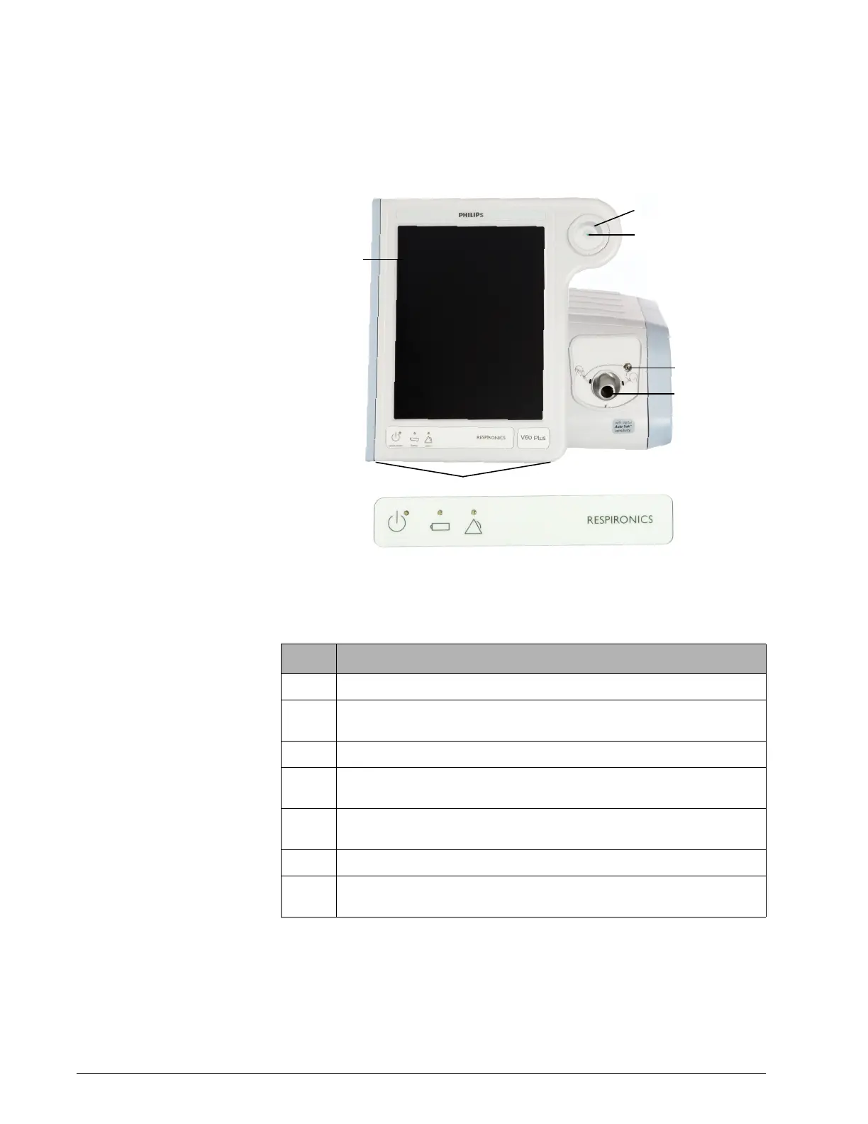
Ventilator unit
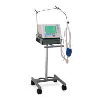
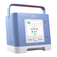
Figure 3-3 through Figure 3-5 show the controls, indicators, and other
important parts of the ventilator unit.
Figure 3-3: Front view
Number Description
1 Graphical user interface. Color LCD (liquid crystal display) with touchscreen.
2 Navigation ring. Lets you adjust values and navigate the graphical user interface
by rotating the finger on its touchpad.
3 Accept button. Activates selections.
4 Proximal pressure port. Connection for tubing that monitors patient pressure in
the patient circuit.
5 Ventilator outlet (To patient) port. Main connection for the patient circuit. Deliv-
ers air and oxygen in prescribed pressures to the patient.
6 Alarm speakers (beneath ventilator)
7 Alarm LED. Flashes during a high-priority alarm. On continuously during a venti-
lator inoperative condition.