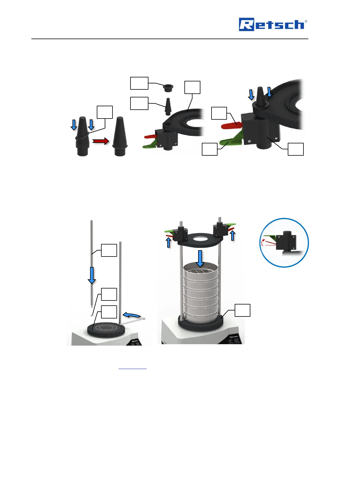
Place the assembly aid ring (MH1) on the assembly aid (MH2) and slide it down. This
presses the O-ring on the quick clamping unit and fixes the clamping lid.
Repeat this procedure for the other side.
Fig. 6: Assembly of the clamping lid
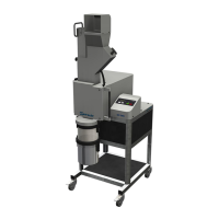
Screw one hexagonal nut (G) on the thread of each of the support rods (E).
Screw both support rods (E) into the designated threaded holes (SB) in the sieve plate (ST)
and lock them with the hexagonal nuts (G).
Firmly tighten the hexagonal nuts (G) by means of a 19 mm open-end wrench.
Fig. 7: Installation of the sieve clamping unit "comfort"
Place the desired sieve stack including the sample material centrally on the sieve plate (ST).
Place the assembled clamping lid on the support rods (E) with the quick clamping units
facing upwards.
Lift the red quick clamping levers (F2) of both quick clamping units (F) for freely sliding the
clamping lid up and down the support rods. Be sure not to push down the green quick
clamping levers when doing so.
Slide the quick clamping units with the clamping lid down the support rods (E) onto the top
test sieve.
When the clamping lid is correctly positioned on the sieve stack, press down the green quick
clamping levers (F1) 1 – 2 times in order to fix the clamping lid tightly on the sieve stack.