5.1 Sieve Clamping Unit "economy" and "standard"
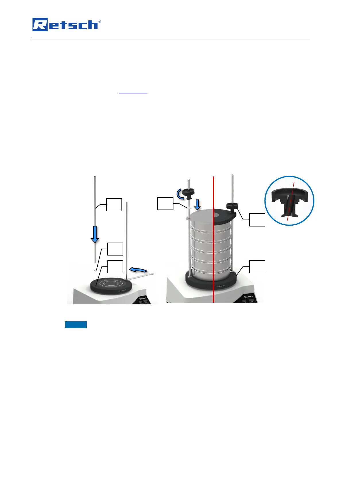
Screw one hexagonal nut (G) on the lower end of each of the threaded rods (A).
Screw both threaded rods (A) into the designated threaded holes (SB) in the sieve plate (ST)
and lock them with the hexagonal nuts (G).
Firmly tighten the hexagonal nuts (G) by means of a 19 mm open-end wrench.
Place the desired sieve stack including the sample material centrally on the sieve plate (ST).
Lay the clamping lid "economy" (C) or "standard" (D) over the threaded rods (A) onto the top
test sieve. The top side of the clamping lid "economy" is marked by the Retsch GmbH logo.
The clamping lid "standard" is orientated so that the peripheral edge surrounds the test
sieves.
Place the washers (B1) over the threaded rods (A) on top of the clamping lid "economy".
Slide the fixing nut (B) in an inclined position of 10° down the threaded rod (A) onto the
clamping lid.
Align the fixing nuts (B) vertically so that the thread engages and tighten the fixing nuts
hand-tight.
NOTICE To clamp a maximum of five test sieves and a collecting pan, shorter threaded rods
are available for the sieve clamping units "economy" and "standard". For sieving processes with
only one to three test sieves, the shorter threaded rods should be used. Long, projecting
threaded rods disturb the spreading of the sample material due to their natural vibration
behaviour.
5.2 Sieve Clamping Unit "comfort"
Put both quick clamping units (F) on a flat surface with the green quick clamping lever (F1)
facing down.
Place the clamping lid (D) with the top side (plane side) face down on the quick clamping
units (F).
Place the O-ring (OR) on the cone shaped assembly aid (MH2) and slide it down into the
designated groove.
Put the assembly aid (MH2) in the opening of the clamping lid (D) in such a way that the
cone shaped tip is sticking out.