Rexroth EcoDrive 03 DKC**.3-040...200 Instructions for Use 5-13
DOK-ECODR3-DKC40*200UL-IB01-EN-P
max. voltage at X6.5/7 against X6.6/8: DC 40 V
current consumption at X6.5 and needed supply
voltage:
see "Technical data" brake
in the motor manual
max. allowed current load when looping through
brake supply over X6.5/6 to X6.7/8:
DC 10 A
wire cross section:
min. 1 mm²
for looping through: min. 2.5 mm²
Voltage resistance of single wire to ground
> 750 V
(e.g.: litz wires - H07)
wire routing
parallel if possible
(twisted)
max. inductance between 24 V source and
X6
100 µH
(equals about 2 x 75 m)
CAUTION
Risk of damage!
⇒
Risk of damage by increased transition resistance in
the case of strong mechanical influence at the test
tap.
Motor holding brake
The controller controls the holding brake.
Supply voltage, current consumption, linking, separating time, holding
torque, etc. see motor manual.
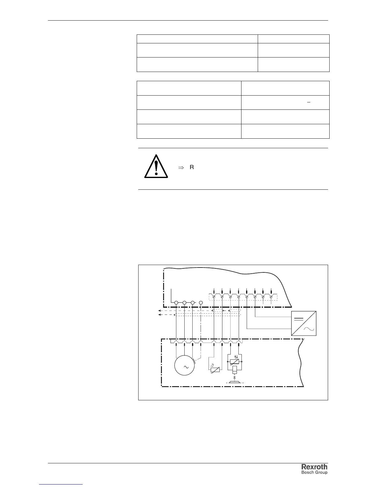
Basic connection of motor power, holding brake and
motor temperature monitoring
AP5107F1.FH7
3
4
1
2
F
G
AC-Motor
M
3
A1 A2 A3
A
B
C
D
X6
E
H
5
6
TM+
TM-
BR+
BR-
U
B
0VB
24V
Ext
0V
Ext
DKC
XE1
X5
7
8
0VB
UB
24V
XS1
Temperature
dependent resistance
Holding
brake
U
Fig. 5-29: Connection of motor cable, holding brake and temperature monitor
for motors with connectors
Voltage connection for brakes
on DKC:
Wire
voltage connection for brake:
Controlling the motor holding
brake:
Technical data
Motor holding brake: