5-16 Instructions for Use Rexroth EcoDrive 03 DKC**.3-040...200
DOK-ECODR3-DKC40*200UL-IB01-EN-P
Cross section
single wire
[mm²]
Cross section
multi core wire
[mm²]
Cross section
in AWG
Gauge no.:
-- 10 - 25 --
Fig. 5-36: Connection cross section
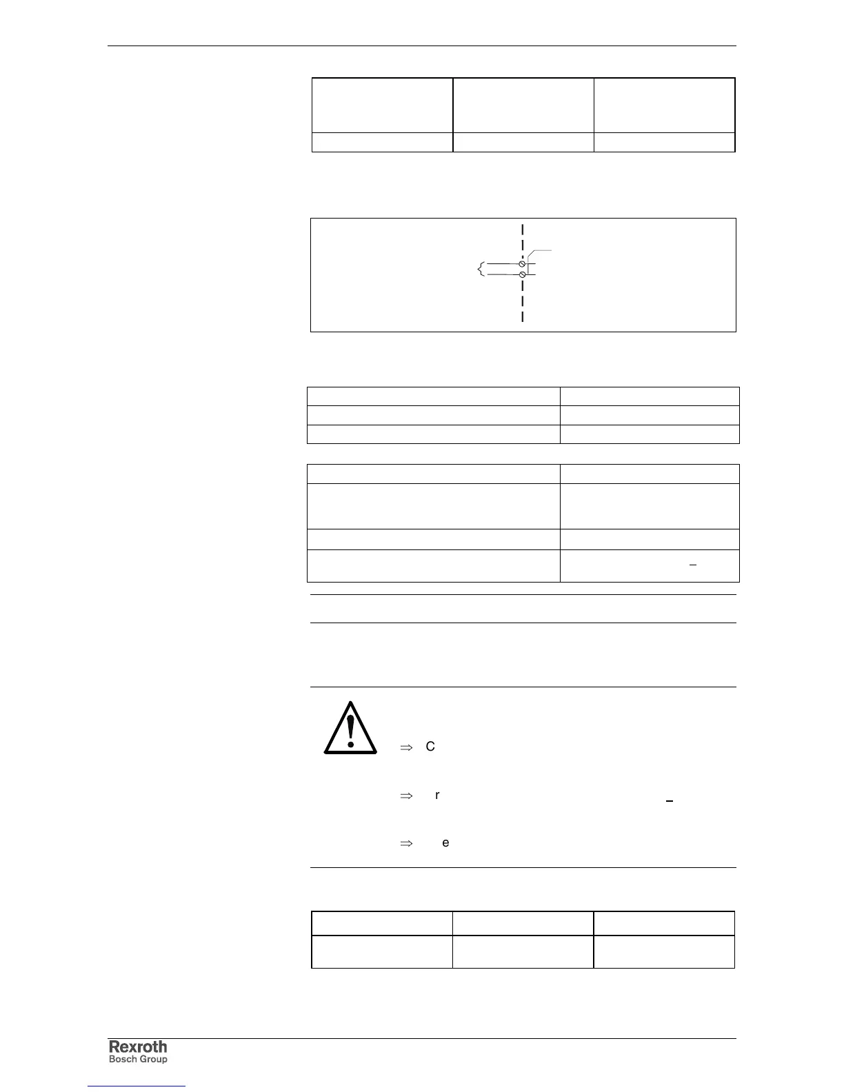
Connection Choke (DR+, DR-)
AP5295F1.FH7
choke connection
device-external device-internal
X12
DR+
DR-
1
2
Fig. 5-37: Optional choke connection for DKC**.3-200-7
At delivery: with bridges at: X12.1 to X12.2
max. voltage against L-: DC 900 V
voltage against ground Applied mains voltage
max. continuous current (rms): 70 A
wire length:
max. 10 m
wire cross section:
min. 10 mm²,
but not smaller than mains
wire cross section
wire routing
twisted
voltage resistance of single litz to ground:
> 750 V
(e.g.: litz wires - H07)
Note: Connection bridged at delivery.
XE1, XE2 Protective Conductor Connections for Motor and Mains
DANGER
Lethal electric shock caused by live parts with
more than 50 V!
⇒
Connect the protective conductor connections of the
drive controller to the protective conductor system of
the control cabinet.
⇒
Cross section of protective conductor: > 10 mm²
(Reason: high leakage currents (EN 50178/1998,
section: 5.3.2.1)
⇒
Check the continuity of the protective conductors
from the mains connection to the connected motors.
Technical description of connector
Type No. of pins Design
screw-in connection 1 screw-in connection for
ring terminals M5
Fig. 5-38: Design
Connection cross section:
Connection
DR+, DR-:
Loadability of the connection
DR+, DR-:
Wire
DR+, DR-:
Design: