Rexroth EcoDrive 03 DKC**.3-040...200 Instructions for Use 5-3
DOK-ECODR3-DKC40*200UL-IB01-EN-P
X1, Connections for Control voltage
Technical description of connector
Ap5264f1.FH7
1234
5678
Fig. 5-3: Connector X1
Type No. of pins Design
Spring contact 2 x 4 Bushing on connector
Fig. 5-4: Design
Cross section
single wire
[mm²]
Cross section
multi core wire
[mm²]
Wire size
in AWG
Gauge no.:
0,2-2,5 1,5-2,5 16-12
Fig. 5-5: Connection cross section
24V control voltage supply (+24V and 0V)
AP5121F1.FH7
+24V
+24V
0V
0V
X1
2
1
3
4
5
8
7
6
device-external device-internal
connection for control voltage
connection for control voltage to additional DKCs
Fig. 5-6: Connections for control voltage
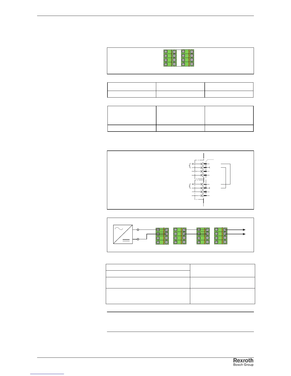
Ap5139f1.fh7
X1
X1
1234
5678
24V
1234
5678
to additional
devices
Fig. 5-7: Looping through control voltage
Voltage at X1/1 against X1/2:
Current or power consumption X1/1:
See chapter "Ratings and
Dimensions"
Reverse voltage protection: Via allowed voltage range using
internal protection diodes
Max. allowed current load when looping
through the control voltage via X1.1/2 to
X1.5/6:
DC 10 A
Note: Strong mechanical influence on the test tap of the terminals
can increase the transition resistance and destroy the
terminals.
Illustration:
Design:
Connection cross section:
Connection
+24V and 0V:
Connection loads
+24V and 0V: