5-4 Instructions for Use Rexroth EcoDrive 03 DKC**.3-040...200
DOK-ECODR3-DKC40*200UL-IB01-EN-P
Note: The input 0 V is connected directly to the device potential. The
utilization of an insulation monitoring for +24 V and 0 V against
device is therefore not possible!
wire cross section: min. 1 mm²
for looping through: min. 2,5 mm²
wire routing: parallel if possible
Max. allowed inductance between 24V
source and X1:
100 µH
(equals about 2 x 75 m)
Note: If the cross sections of the lines for looping through the control
voltage are too small, the terminals can be damaged.
Note:
• Exceeding allowed control voltage generates error
message "+24 volt error". (=> See also firmware functional
description.)
• Control voltage failure causes the running motor to coast
torque-free (without brake).
DANGER
Dangerous movements due to unbraked
coasting of motor with control voltage failure!
⇒
Personnel should not remain within the area of the
machine with moving parts. Possible preventive
steps against unauthorized access are:
– protective fencing
– bars
– covers
– light barriers
⇒
The fences must be able to withstand the maximum
possible force that the machine can generate.
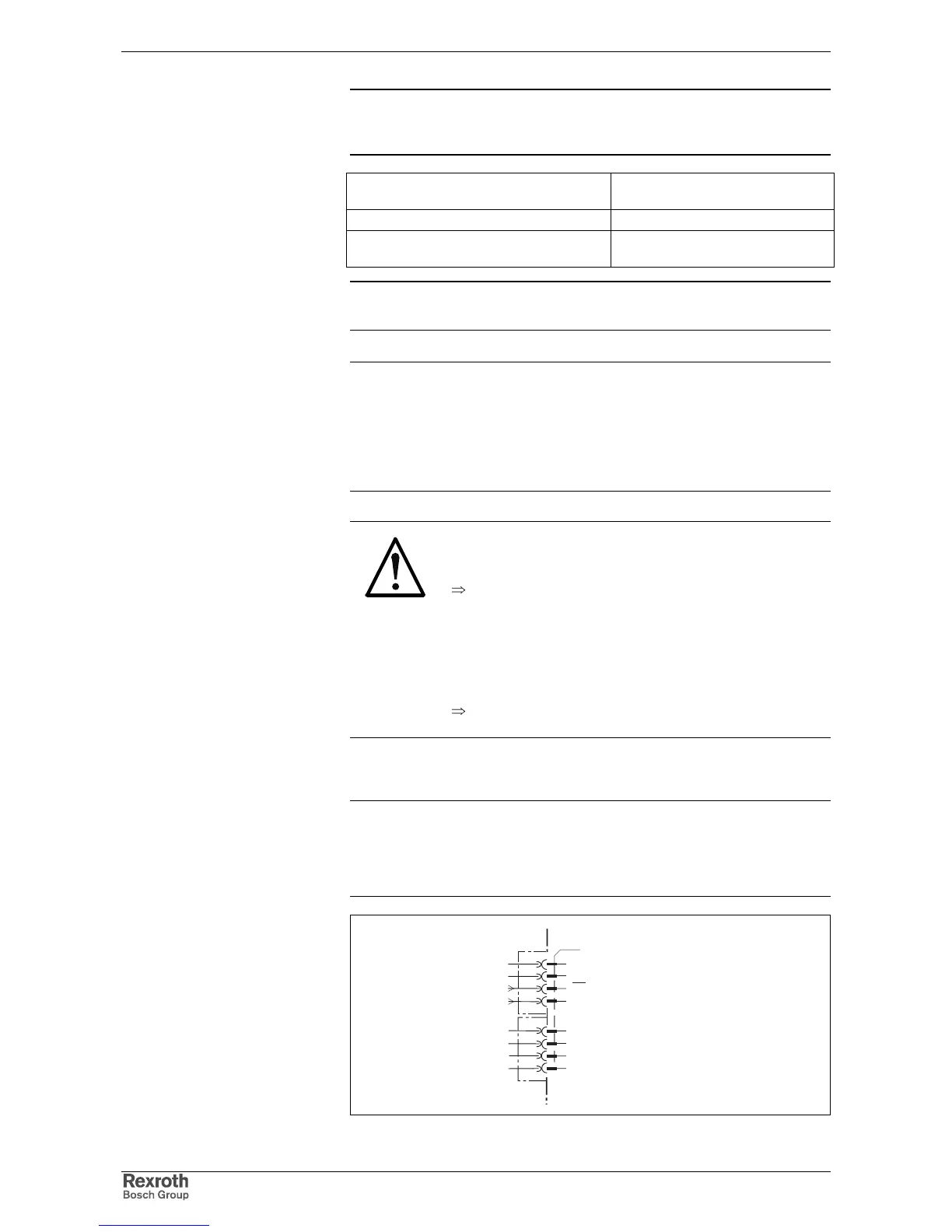
Drive halt (AH) and Drive enable (RF)
Note:
• Inputs work with inactive bus communication.
• Inputs don't work with active bus communication (SERCOS
interface, Profibus-DP, ...).
AP5270F1.FH7
AH
drive halt
RF
drive enable
X1
2
1
3
4
5
8
7
6
device-external device-internal
Fig. 5-8: Connections for drive halt and drive enable
wire
+24V and 0V:
Connection
AH and RF: