Rexroth EcoDrive 03 DKC**.3-040...200 Instructions for Use 5-5
DOK-ECODR3-DKC40*200UL-IB01-EN-P
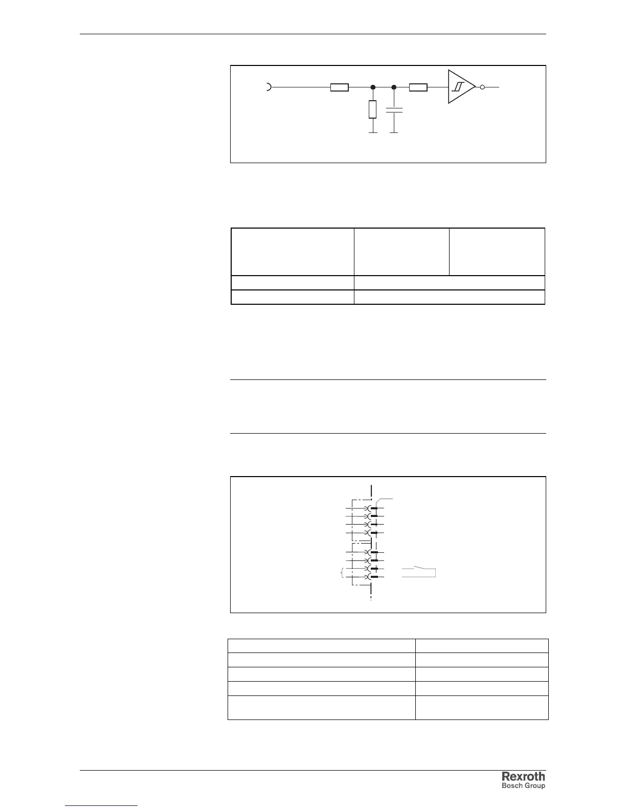
R1 R3
R2
C1
I
n
Ap5183f1.fh7
Schematics
R1: 10k
R2: 3k3
R3: 10k
C1: no data
Fig. 5-9: Input circuit
Input voltage:
High
Low
min.
16 V
-0.5 V
max.
30 V
3 V
Input resistance 13.3 kOhm ±5%
Reaction time See firmware functional description
Fig. 5-10: Inputs
The drive halt function is used to bring an axis to standstill with defined
acceleration and jerk (see firmware functional description).
The input drive enable (RF) activates the drive with a 0-1 edge.
Note: If the inputs are controlled by a power supply other than the
DC24 volt supply of the drive controller, then the reference
lead of the other power supply must be connected to X1.2
(0 V).
Ready to operate contact Bb
X1
2
1
3
4
5
8
7
6
Bb
Bb
ready for operation
AP5122F1.FH7
device-external device-internal
Fig. 5-11: Connections for ready to operate contact
max. switching voltage: DC 40 V
max. switching current: DC 1 A
max. continuous current: DC 1 A
minimum contact load: 10 mA
Guaranteed number of switching operations
at max. time constant of load < 50 ms:
250,000
Input circuit
AH and RF:
Inputs
AH and RF:
AH:
RF:
Connection
Bb:
Loadability of the connection
Bb: