5-14 Instructions for Use Rexroth EcoDrive 03 DKC**.3-040...200
DOK-ECODR3-DKC40*200UL-IB01-EN-P
AP5125F1.FH7
3
4
1
2
AC-Motor
M
3
A1 A2 A3
U1
X6
5
6
TM+
TM-
BR+
BR-
U
B
0V
B
24VExt
0VExt
DKC
XE1
X5
7
8
0V
B
U
B
24V
XS1
V1
W1
X1 X2
T1
T2
U
BR-
BR+
Temperature
dependent resistance
Holding
brake
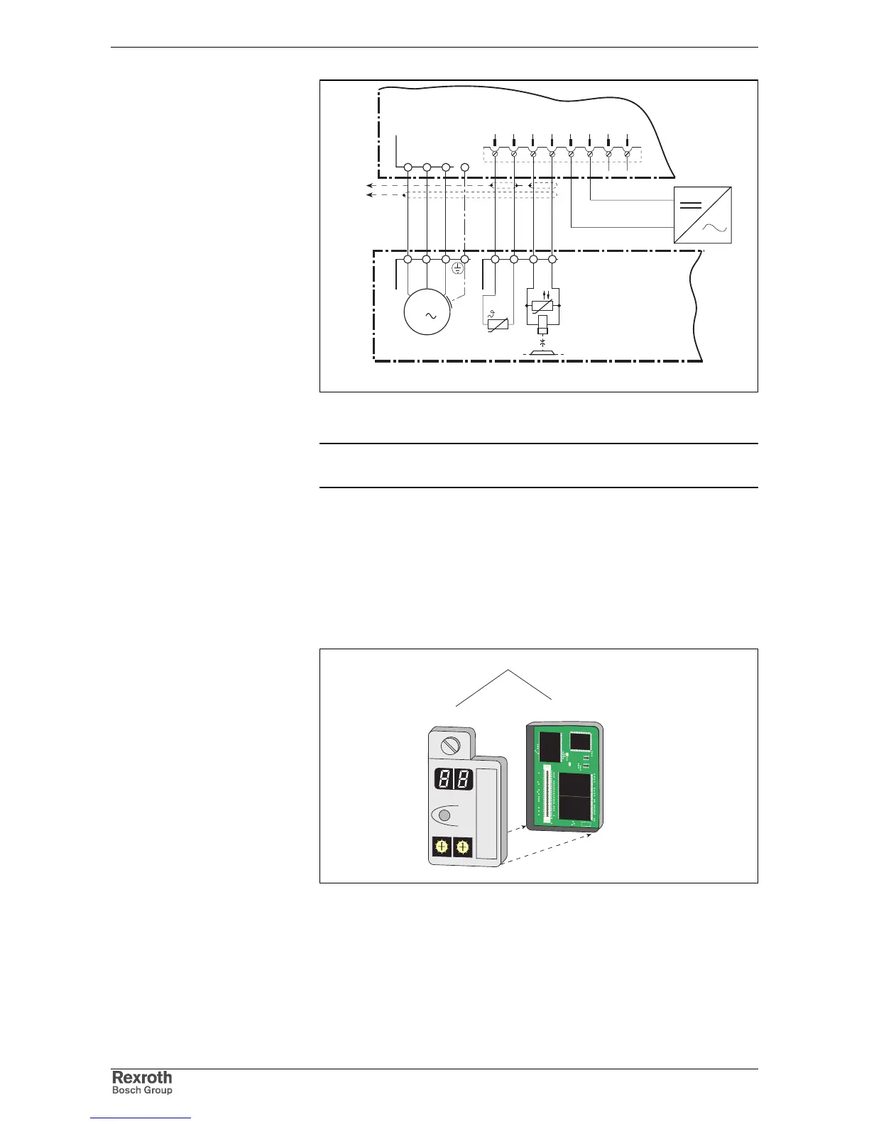
Fig. 5-30: Connection of motor cable, holding brake and temperature monitor
for motors with connector box
Note: The cable designations and all details on making cables are
outlined in the cable or motor document.
X7, Connection for Programming module
Programming module
The programming module can be broken down into
• Parameter module for user-specific parameters
• Firmware modules for unit-specific firmware
Ap5146f1.fh7
Programming module
Firmware module
Parameter module
Barcode
0
1
2
3
4
5
6
7
8
9
0
1
2
3
4
5
6
7
8
9
H1
S1
S3
S2
Barcode
H1
S1
S3
S2
0
1
2
3
4
5
6
7
8
9
0
1
2
3
4
5
6
7
8
9
ISSI
IS61C6416-20T
C2110900 9728
splSI2032
110LT48
H813A08
ESF2
SDS
Fig. 5-31: X7, Programming module
H1: Diagnostic display
S1: Reset key
S2, S3: Address switch