Rexroth IndraDrive C Electrical Data 6-21
DOK-INDRV*-HCS02.1****-PR02-EN-P
6.9 Connections
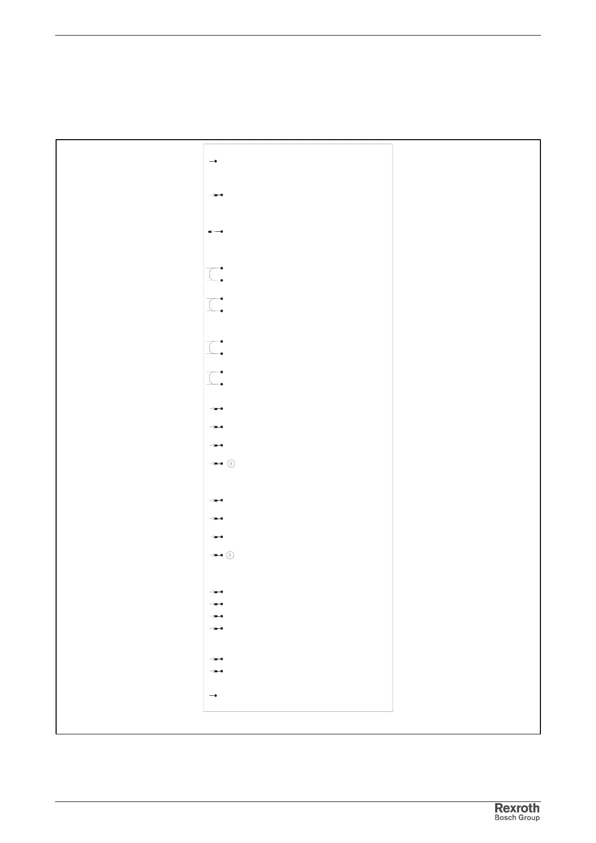
Complete Connection Diagram
anschlussplan_w0054u70.fh7
shield connection
XS1
bus connection OUT
X1:Out
X1out 1-8
X1:In
X1in 1-8
control voltage
X13:1 0V
X13:2 0V
X13:3 +24V
X13:4 +24V
DC bus
L+
L+
L-
L-
mains connection
L1
X3 L1
L2
L2
L3
L3
motor connection
A1
X5 A1
A2
A2
A3
A3
motor temperature monitoring
motor holding brake
MotTemp+
X6 1
MotTemp-
2
+24VBr
3
0VBr
4
external braking resistor
1
X9 1
2
2
XS2
bus connection IN
shield connection
X1, L+/L not available for HCS02.1E-W0012
X9 not available for HCS02.1E-W0012 and –W0028
Fig. 6-21: Complete connection diagram
 Loading...


