Translation of the Original ENGLISH DESCRIPTION OF THE P030 CHILLER
454522.68.07-01-E
13
27.06.2012
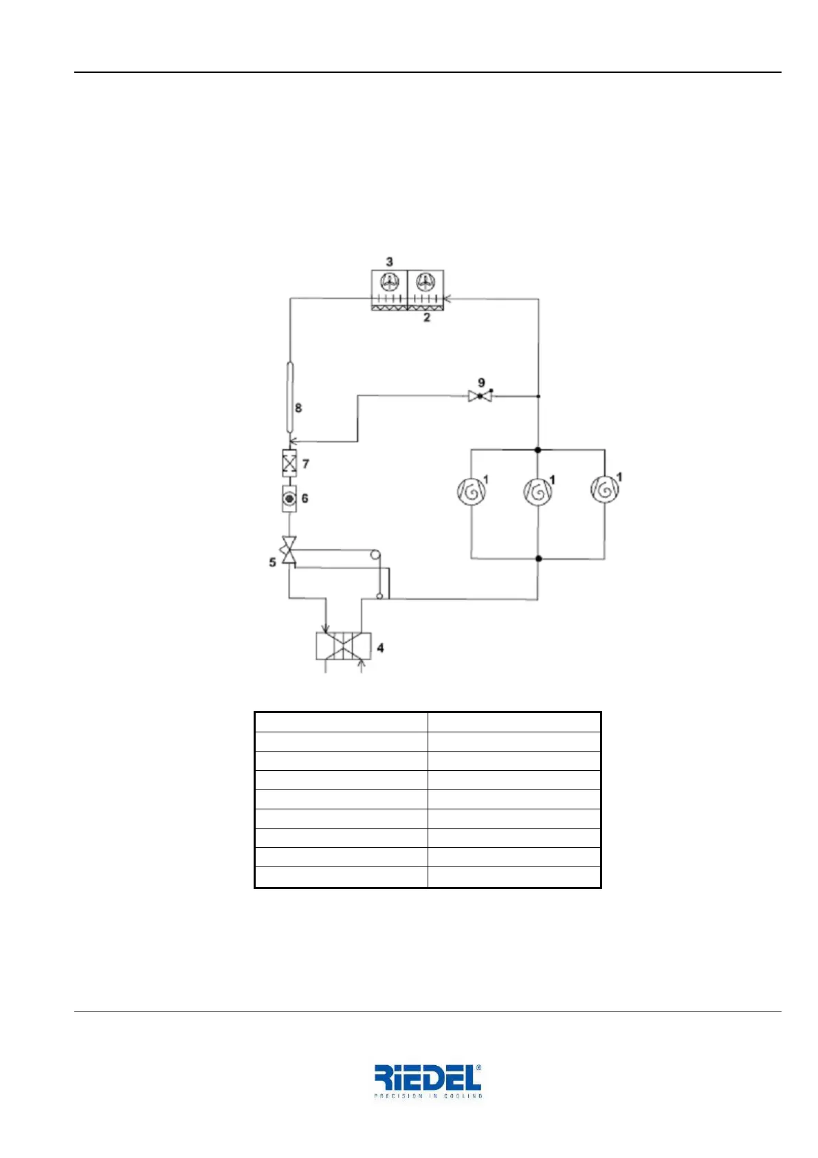
The vaporised refrigerant is drawn in by the three compressors (1) and is then compressed (rise in
pressure and temperature). The refrigerant also absorbs the heat of the compressor motor, and this
heat is given off to the surrounding air by the condenser (2) – in the form of waste heat – by means
of the two fans (3).
The refrigerant is thus liquefied and passed to the inlet of the expansion valve (5) via the liquid
receiver (pipe expansion), the filter drier (7) and the sight glass (6). The expansion valve permits
liquid refrigerant to enter the evaporator as a function of the temperature.
Block flow diagram, Refrigeration Circuit
1. Compressor
2. Condenser
3. Fan
4. Evaporator
5. Expansion valve
6. Sight glass
7. Filter drier
8. Pipe expansion (receiver)
9. Hot gas bypass valve