MOUNTING ENGLISH Translation of the Original
26
454522.68.07-01-E
27.06.2012
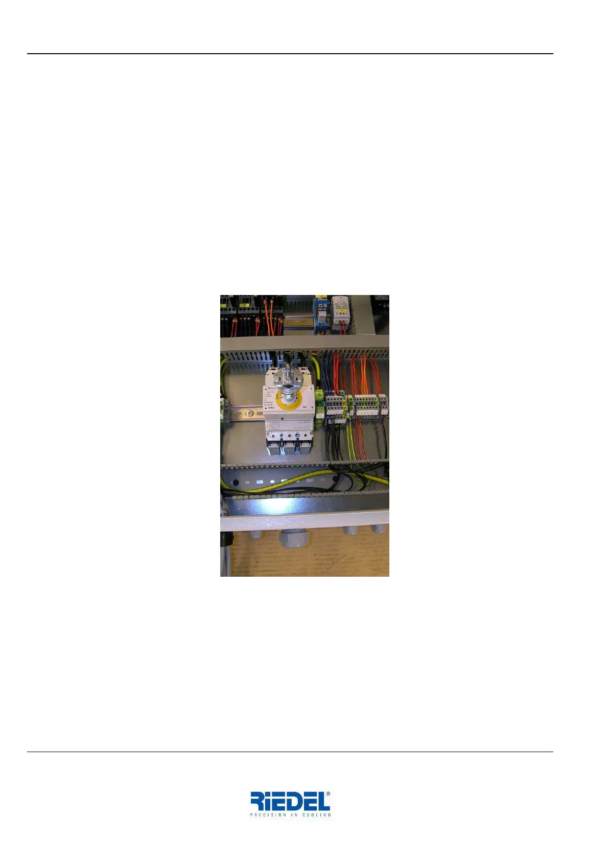
6.2 Electro-Technical Connection
Activities to be performed:
− Open, disengage and remove panel assembly on the operating side using the supplied key
− Open the control cabinet door using the supplied key.
− Working from below, pass the connecting cable through the cable bushing provided in the base
plate
− Route cable properly inside the P030 Chiller and insert it in the control cabinet by passing it
through the screwed cable gland
− Establish electro-technical connection in accordance with the circuit diagram (see Appendix)
− The P030 Chiller is ready for connection to a remote control unit. In the delivery state a jumper
wire is inserted across the terminals. The general fault indicator is wired to the terminal in the
form of a potential-free contact. (See also circuit diagram in the Appendix).
− Close and lock the control cabinet door.
− Engage and lock the panel assembly.
6.3 Optical Fibre Connection
Activities to be performed:
− Open, disengage and remove panel assembly on the operating side using the supplied key.
− Working from below, pass the optical fibre cable through the cable bushing provided in the base
plate, route it properly and insert it in the control cabinet by passing it through the screwed
cable gland.
− Establish the connection in accordance with the enclosed installation instructions.
− Remove mating optical fibre component for the COO from the control cabinet and install it in the
COO.
− Install panel assembly, close the control cabinet door and lock both using the supplied key.