43
20033283
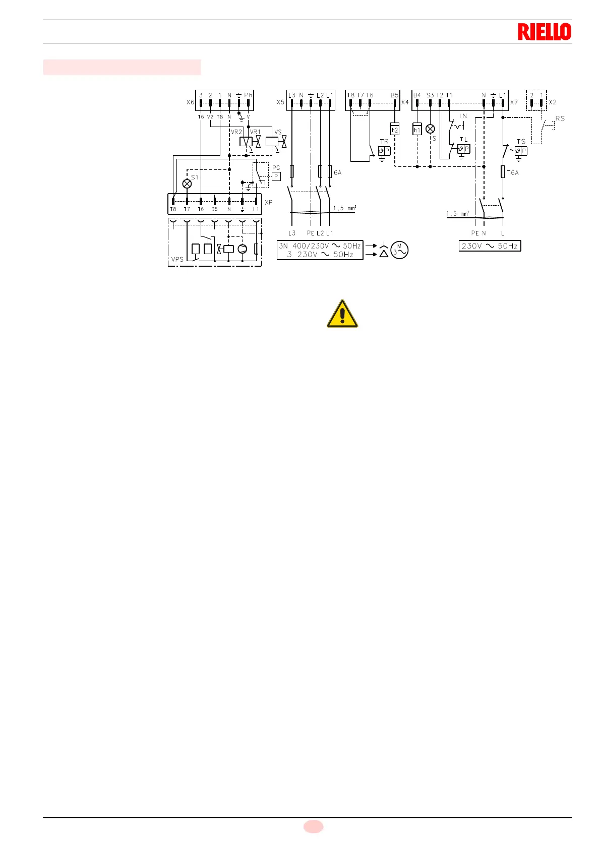
Appendix - Electrical panel layout
Key to layout (Fig. 4 - Fig. 5 - Fig. 6 - Fig. 7)
h1 - 1
st
stage hour counter
h2 - 2
nd
stage hour counter
IN - Burner manual stop switch
XP - Plug for leak detection control device
X2 - 2 pole plug (if present)
X4 - 4 pole plug
X5 - 5 pole plug
X6 - 6 pole plug
X7 - 7 pole plug
PG - Min. gas pressure switch
RS - Remote lock-out reset button (if present)
S - Remote lock-out signal
S1 - Remote lock-out signal of leak detection control device
TR - High-low mode load remote control system:
controls operating stages 1 and 2.
If the burner is to be set up for single stage operation, re-
place the remote control device TR with a jumper.
TL - Load limit remote control system:
shuts down the burner when the boiler temperature or
pressure reaches the maximum preset value.
TS - Safety load control system:
operates when TL is faulty
VR1 - Adjustment valve 1
st
stage
VR2 - Adjustment valve 2
nd
stage
VS - Safety valve
Fig. 7
WITH VPS LEAK DETECTION
CONTROL DEVICE
D3492
RLS 50 (three-phase power)
Gas valve leak detection control takes place im-
mediately before every burner starting.