9
20140262
Technical description of the burner
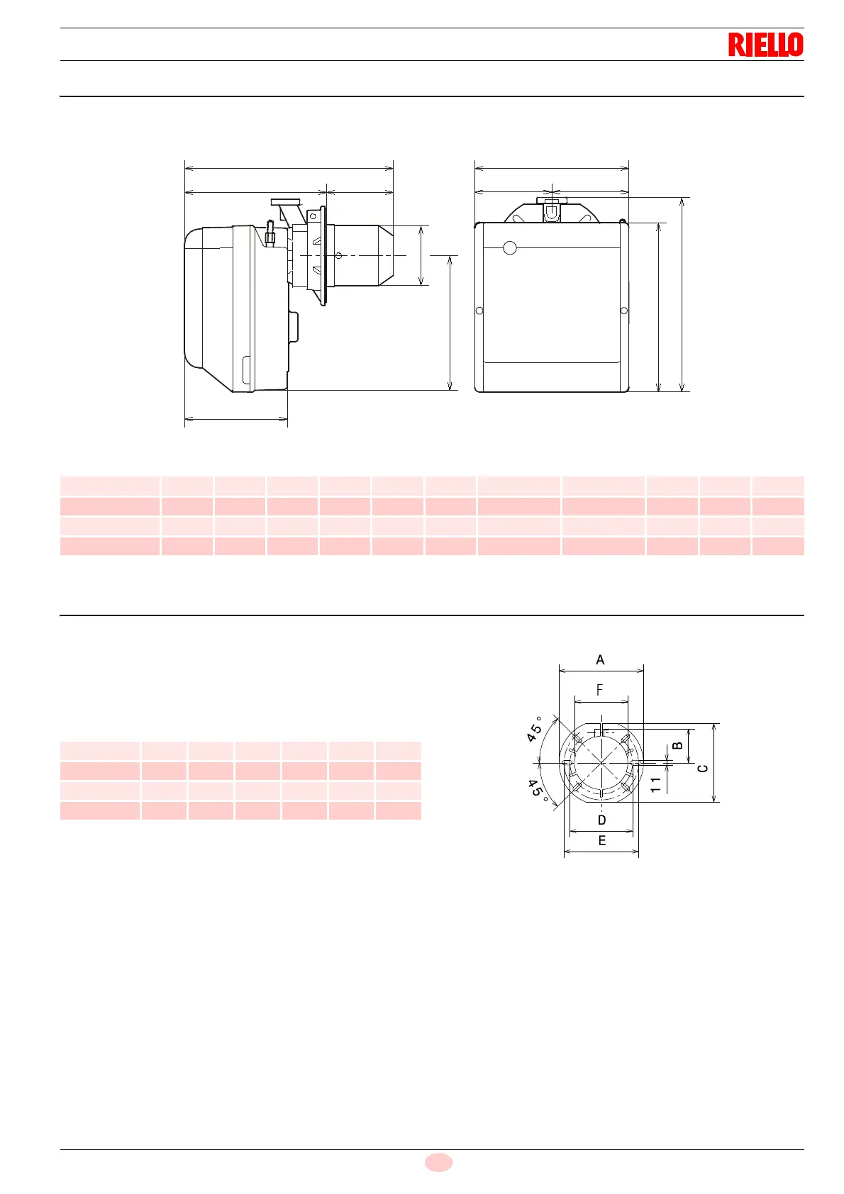
4.6 Maximum dimensions
The maximum dimensions of the flange and burner are given in
Fig. 1.
Tab. F
4.7 Preparing the boiler
4.7.1 Boring the boiler plate
Pierce the closing plate of the combustion chamber, as in Fig. 2.
The position of the threaded holes can be marked using the ther-
mal insulation screen supplied with the burner.
Tab. G
Model A B C D E F G H I ø L M
BS1F 234 254 295 122.0 112.0 346 230 276 116 70 174 89 210
BS2F 255 280 325 125.5 125.5 352 238 252 114 100 174 106 230
BS3F 300 345 391 150.0 150.0 390 262 280 128 110 196 129 285
BS4F 300 345 392 150.0 150.0 446 278 301 168 145 216 137 286
Model A B C D E F
BS1F 192 66 167 140 170 89
BS2F 192 66 167 140 170 106
BS3F 216 76.5 201 160 190 129
BS4F 218 80.5 203 170 200 137