20140262
24
Installation
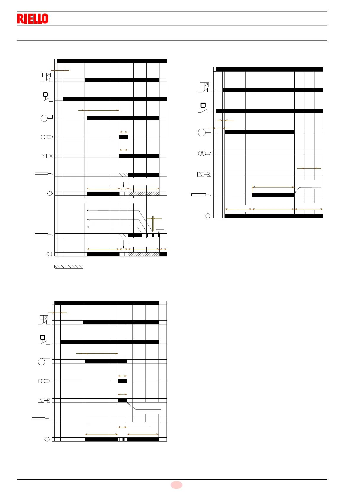
5.12 Operating programme
Key
FM –Fan motor
HT – Heat request
ID – Ignition device
LED – LED colour inside the button
PG – Low gas pressure switch
SO – Ionisation probe
t1 – Standby time
t2 – Initialisation time for checking
t3 – Pre-purging time
t3l – Checks for presence of extraneous light during pre-purg-
ing phase
t4i – Total ignition time
t4l – Reaction time to achieve safety lockout due to lack of fail-
ure
ts – Safety time
V1 – Gas valve
t
2
t
1
t
3
t
4i
t
s
HT
FM
ID
V1
LED
P
M
LED
t
4l
PG
P
SO
SO
POWER SUPPLY
Signal not requested
Blink
Orange
Green blink
Lockout
Green
No flame during operation
Green blink
Green
Fig. 20
Normal operation
20136055
Blink
Orange
Blink
fast red
t2
t1
t3
t4i
ts
HT
FM
ID
V1
LED
P
M
PG
P
SO
Lockout
Green blink
Red
Blink
Orange
Lockout due to ignition failure
20136056
POWER SUPPLY
Fig. 21
LED
t
2
t
1
HT
FM
ID
V1
P
M
t
3
l
PG
t
s
P
SO
Red, green blink
Lockout
Red
Lockout due to extraneous light during pre-purging
POWER SUPPLY
Fig. 22
20136057
Blink
Orange