ELECTRICAL CONNECTIONS
CONNECTION CABLES SECTION
Refer to the following table for the sizing of input, output and battery cables:
network / separate bypass (optional)
(1)
The sections contained in the table refer to a maximum length of 10 m (cable type N07V-K in clear air)
(2)
The maximum length of the connection cables to the Battery Box is 10 metres
(3)
In the case of non-linear loads, oversize neutral line N by 1.7 times the phase line
Note MST 60: the maximum section of the cables that can be inserted in the terminal board is equal to 50 mm2 (flexible and
rigid cables)
MST 80: the maximum section of the cables that can be inserted in the terminal board is equal to 95 mm2 (flexible and
rigid cables)
MST 100 : the maximum cross-section of the cables to insert into the terminals is 95 mm² for the PHASES and 150 mm²
for the batteries (flexible and rigid cables).
MST 125: the cables must be fitted with crimp headers for M8 bolts.
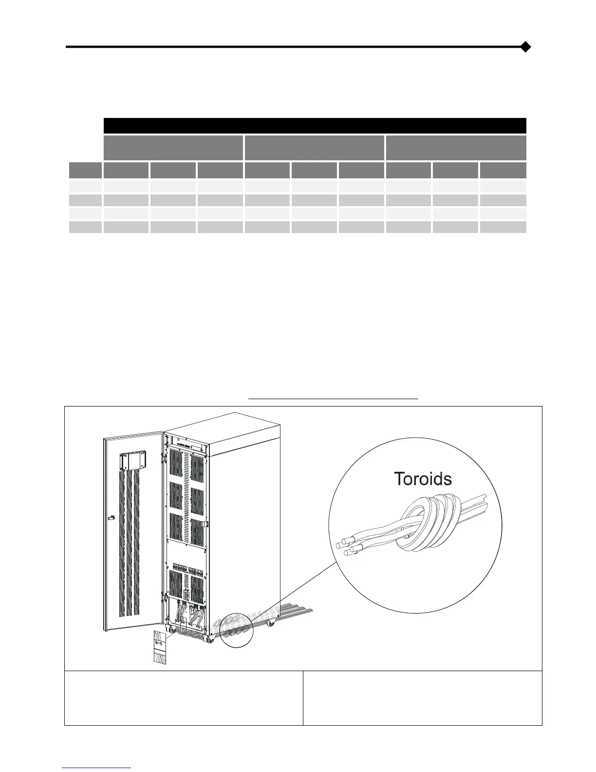
ARRANGEMENT OF THE CABLES AND INSERTION OF THE FERRITE TOROIDS
It is recommended to wire the power cables routing them from the back, under the UPS, to the front of the machine, ensuring they
come up in the terminal area.
Insert the ferrite toroids supplied as shown below (NOTE: ferrites cannot be fitted to the MST 125)
Insert 3 toroids into the cable bundle [L1, L2, L3, N] INPUT
Insert 3 toroids into the cable bundle [L1, L2, L3, N] OUTPUT.
Arrange the cables so that the toroids are positioned under the
base of the UPS or close to it.
Insert 4 toroids into the cable bundle [L1, L2, L3, N] INPUT.
Insert 4 toroids into the cable bundle [L1, L2, L3, N] OUTPUT.
Arrange the cables so that the toroids are positioned under the
base of the UPS or close to it.