Installation
72
EN
2.11 ELECTRIC CONNECTIONS AND DIAGRAMS
The wiring diagrams of RIELLO
NXC/NXH devices are sup-
plied with the unit. Please refer to them if necessary.
NXC/NXHleavesthefactoryfullywiredandrequires
onlyaconnectiontotheelectricalpowergrid,theinstalla-
tion
ofapadlockabledisconnectingswitch,andconnections
toanyaccessorycomponents.
Inordertoaccessthecontrolpanel'sterminalblocks:
• setthesystem'smainswitchtoits"OFF"position,andthe
device'smainswitchtoits"0"(off)position
ON
OFF
•
loosenthefasteningscrewsusingascrewdriverwithma-
gnetic tip
•
slidethepaneldownward
•
pullthepaneltowardsyou.
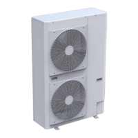
NXC 017-021
2
1
1.Powerconnectioninput
2.Auxiliaryconnectioninputs
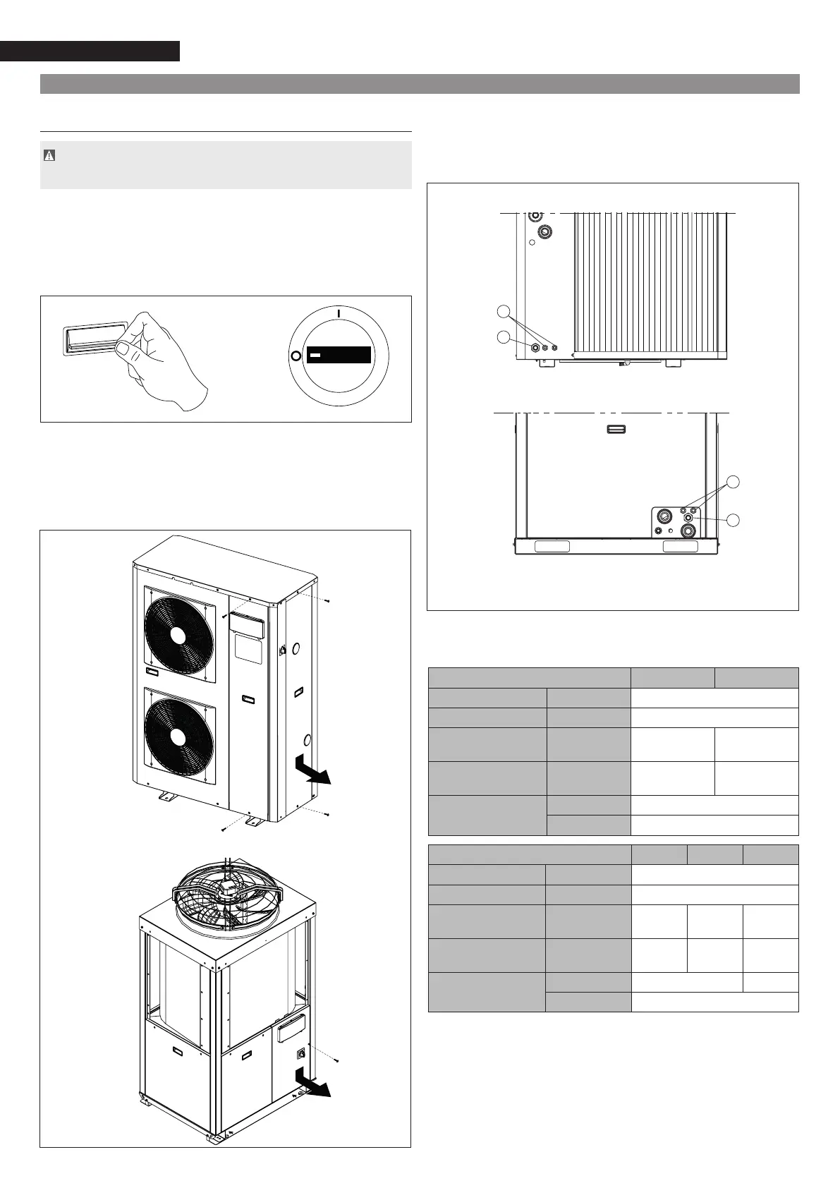
2
1
•
routethepowercablethroughthecablegland(2)andfa-
sten it
• r
oute the cables for connecting the auxiliary components
throughthecableglands(1)andfastenthem
NXC 017-021
Forthesizingoftheelectricalpowercables,usethefollowing
table:
NXC 017 021
Electricalpowersupply V/Ph/Hz+N 400/3/50+N+PE
Permittedvoltage V/Ph/Hz+N 360 - 440
Maximumtotalpower
consumption
kW 7.8 9.1
Maximumtotalcurrent
consumption
A 13 16
Powercable
n.sq.mm 5x6
Type H07RNF
NXC/NXH 026 033 040
Electricalpowersupply V/Ph/Hz+N 400/3/50+N+PE
Permittedvoltage V/Ph/Hz+N 360 - 440
Maximumtotalpower
consumption
kW 11.0 13.8 1 7.5
Maximumtotalcurrent
consumption
A 20 24 30
Powercable
n.sq.mm 5x16 4x16
Type H07RNF
Complete the electric connections, ret all components by
performingthedescribedoperationsinreverseorder.
Checkthat:
• thecharacteristics of theelectricalnetworkaresuitable
forthedevice'susagevalues,alsotakingintoaccountany
othermachinerythatwillbeoperatingalongsideit;
NXC 026-040
NXH 026-040
NXC 026-040
NXH 026-040