97
Alarm codes
EN
6.1 ALARM MENU
The
Pro-Dialog+
panel features many troubleshooting
functions. In case of error, an alarm will be triggered and
its identicationcodewill beloggedintothealarm menu,
CUR_ALRMandALARMRSTsub-menus.
ThecontrolpanelLEDswillsignalthealarms.Itisreminded
that:
• ashing LED indicates that at least one circuit of the
machine
isinoperationbutthereisawarningsituation.
• steadyLEDindicatesthatatleastonecircuitofthemachi-
ne
hasstoppedduetoanerror.
ALARMRST sub-menu shows up to ve alarm codes active
withintheunit.
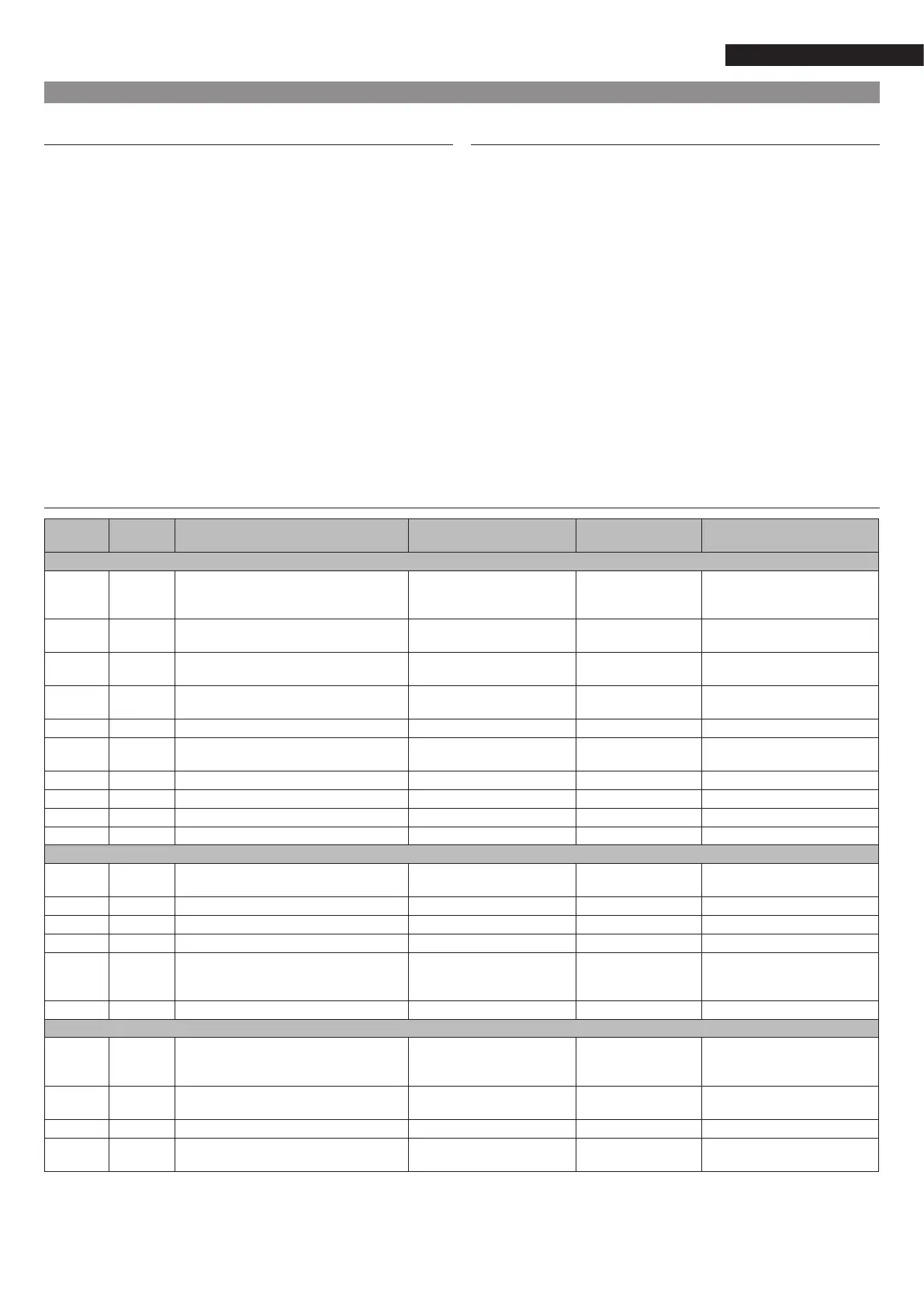
6.3 ALARM CODES
Alarm
number
Alarm code Alarm description Reset mode Probable cause Control system reaction
Thermistor faults
1 th-01 Heatexchangerenteringwatertemperature
sensor fault
Automatic,whenthe
temperaturedetectedisback
to normal again
Thermistor fault Unit stop
2 th-02 Heatexchangerleavingwatertemperature
sensor fault
As above As above As above
3 th-03 Defrost fault of cooling circuit A As above As above Stopofthecircuitifthedeviceis
inheatingmode
4 th-04 DefrostfaultofcircuitBorsecondfaultof
circuit B sensor
As above As above As above
5 th-10 Outdoortemperaturesensorfault As above As above Unit stop
6 th-11 CHWS sensor fault
(Master/Slave)
As above As above Stop of the Master/Slave operation
mode
7 th-12 Circuit A suction sensor fault As above As above Stop of the circuit
8 th-13 Circuit B suction sensor fault As above As above As above
9 th-44 Faultofsuctionsensor,heatexchanger1 As above As above As above
10 th-45 Faultofsuctionsensor,heatexchanger2 As above As above As above
Pressure transducer faults
11 Pr-01 DeliverypressuretransducerAfault Automatic,whenvoltageis
backtonormal
Transducerfaultor
installation error
Stop of the circuit
12 Pr-02 DeliverypressuretransducerBfault As above As above As above
13 Pr-04 CircuitAsuctionpressuretransducerfault As above As above As above
14 Pr-05 CircuitBsuctionpressuretransducerfault As above As above As above
51 Pr-24 Pressuresensorfaultatwaterinlet Automatic,whenthevalueof
thevoltagetransmittedbythe
sensorisbacktonormal
Sensor fault or
installation error
Stop of the circuit
52 Pr-25 Pressuresensorfaultatwateroutlet As above As above As above
Communication with slave boards
15 CO-BB CommunicationlosswithNRCP2board Automatic,when
communications have been
restored
Communication bus
installation error or
slaveboardfault
Compressor A3 or circuit B stop,
accordingtoconguration
16 Co-ht Communicationlosswiththeboardfor
additionalheatingsteps
As above As above Stopofadditionalheatingsteps
17 Co-e1 CommunicationlosswithEXVvalveboard As above As above Unit stop
18 Co-o1 CommunicationlosswithPD-AUX1board As above As above Device stop if equipped with
optionalwaterpressuresensor
6.2 ALARM RESET
Once the error is solved, the alarm code
must be reset. Reset procedure can
bemanualorautomatic,dependingonthetypeofcodeof
alarm. Alarm reset can be carried out al-
so
with machine running. In case of power blackout
the
unitwillautomaticallyrestartwithouttheenablingre-
questfromthecontrolpanel.
Nevertheless,ifthemachine,duringthisinterruption,regi-
sters
somealarms,theycaninhibittheautomaticrestart.
The manual resetprocedure of the alarms must be carried
outfromtheALARMRSTmenu,RST_ALMparameter.However,
accesstothisparametercanbeprotectedbyapassword(that
canbeconguredfromtheGENCONFmenu).