75
PRO-DIALOG+
EN
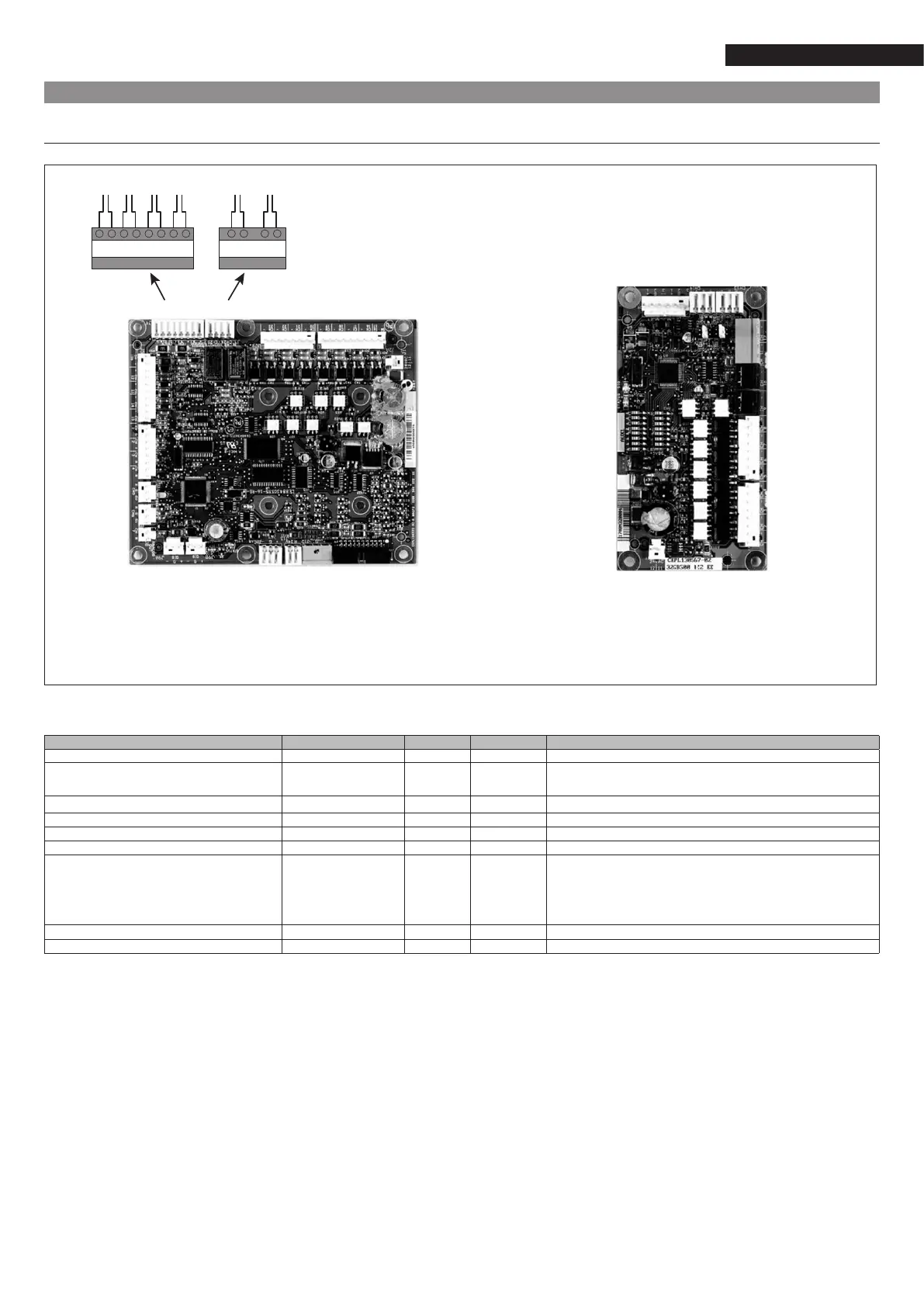
2.11.3 Connections to be performed by the installer
Allconnectionsthatcanbemadethroughtheterminalboardforexternalconnectionsaresummedupinthefollowingtable.
Description Connector/Channel Terminal Board Notes
Contact 1: Run / Stop J4/CH 8 32-33 NRCP2-BASE Usedforoperationmodewithremotecontrol(Remote).
Contact 2: Heating / Cooling selection J4/CH 9 63-64 NRCP2-BASE Usedforoperationmodewithremotecontrol(Remote)
accordingtotheheatgeneratororheatpumpconguration.
Contact3:Selectionofabsorbedpowerlimit1 J4/CH 10 73-74 NRCP2-BASE
Externalsafetyloopinput J4/CH 11A 34-35 NRCP2-BASE
Alarmrelayoutput J3/CH 24 30A-31A NRCP2-BASE
Deviceoperationrelayoutput J3/CH 25 37-38 NRCP2-BASE
ConnectiontoCCNnetwork J12 NRCP2-BASE RS-485 serial connection
- Pin 1: Signal +
- Pin 2: Earth
- Pin 3: Signal -
Output from triac for heat generator control J2B/CH 20 NRCP2-BASE Coolingonlyunit,withoutNRCP2-SLAVEboard
Output from triac for heat generator control J3/CH 5 PD-AUX Heatpumpunit,withoutNRCP2-SLAVEboard.
CR Remote on/off contact
CS Loadlimitationorsetpointmanagementcontact
CRH Heating/coolingmodeswitchcontact
OC Compressor on/off signal output
OA Remote alarm signal output
CCS Systemcontrolcontact
CCS CS CRH CR OA OC
J4 J3 J2B J2A
Scheda
PD-AUX
Scheda
NRCP2-BASE
J3
J12
35 34 74 73 64 63 33 32 30A 31A 37 38