13
20140894
Technical description of the burner
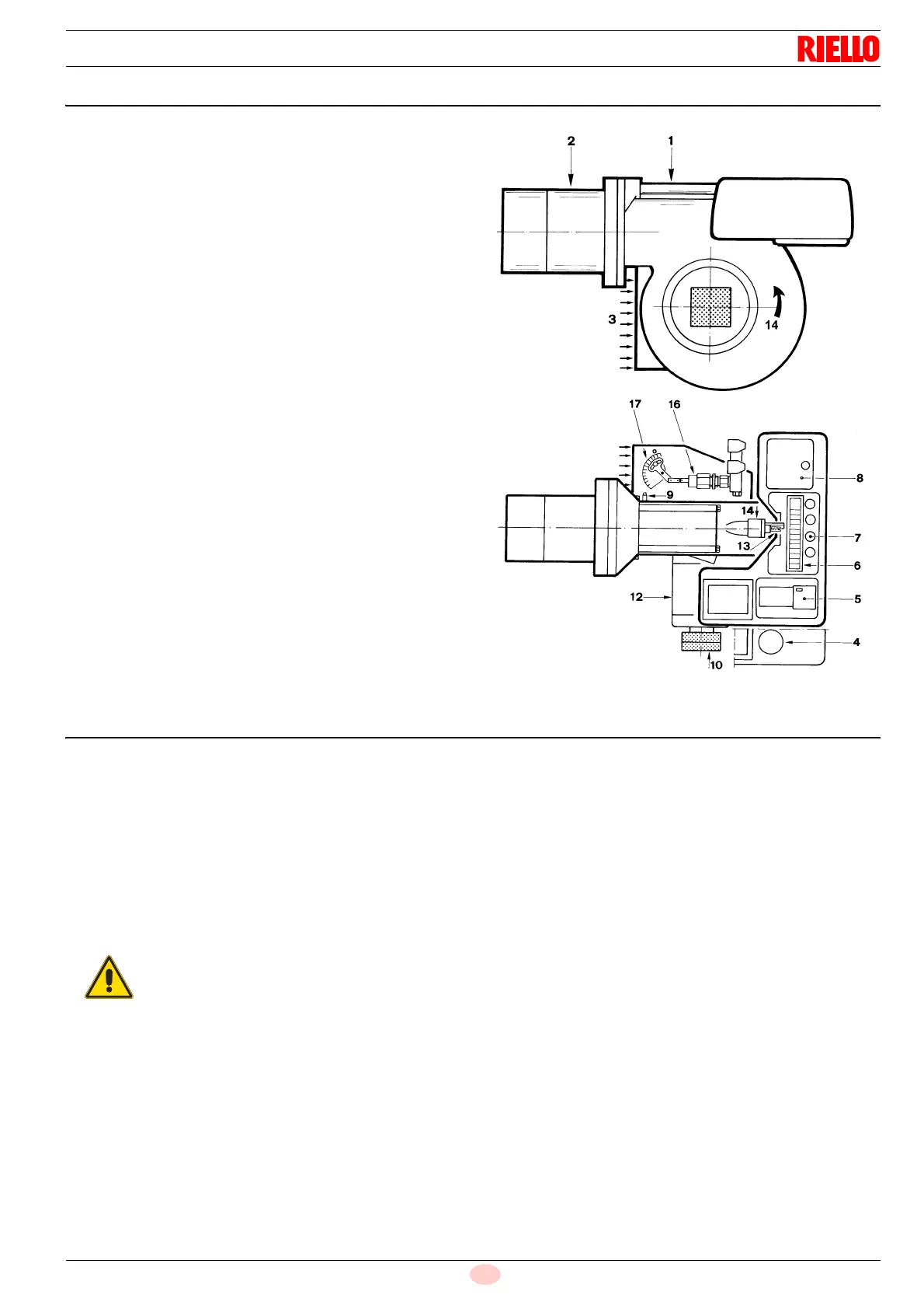
4.8 Burner description
1 Slide bars for opening the burner and inspecting the
combustion head
2 Combustion head
3 Air inlet to fan
4 Motor capacitor
(PRESS GW)
5 Motor contact-maker and thermal cut out with reset button
(PRESS 1G-2G-3G)
6 Terminal strip
7 Fairleads for wiring carried out by the installer
8 Control box with lock-out pilot light and lock-out reset
button
9 Fan pressure test point
10 Pump (see ‘Pump” on page 23)
12 Electrical motor
13 Screw for combustion head adjustment
14 Sensor for flame presence control
15 Fan rotation direction
16 Variable stroke hydraulic cylinder.
Opens the fan gate valve to the value necessary at the
2nd stage of operation.
17 Indexed selector.
This selector adjusts the opening of the fan gate to the
value necessary at the 1st stage of functioning.
Two types of burner failure may occur:
- CONTROL BOX LOCK-OUT:
if the control box 8) (Fig. 7) pushbutton lights up, it indicates that
the burner is in lock-out.
To reset, press the pushbutton for a minimum of three seconds.
- MOTOR TRIP (PRESS 1-2-3 G):
release by pressing the pushbutton on thermal relay 5)(Fig. 7).
4.9 Standard equipment
2 - Hoses
2 - Gaskets for hoses
2 - Nipples for hoses
1 - Reducer with gasket for connection of flexible suction hose
to pump (PRESS 1G-2G)
1 - Thermal insulation screen
4 - Screws to secure the burner flange to the boiler:
M10 x 25 for GW - 1G - 2G
M12 x 40 for 3G
1 - Instruction booklet
1 - Fan for 60Hz use
You must replace burner fan in application with 60
Hz power supply.