23
20140894
Installation
5.10.3 The loop circuit
This is composed by piping that leaves from the tank and returns
to the same with an auxiliary pump that circulates the fuel under
pressure. A branch connection from the loop goes to feed the
burner. This circuit is extremely useful whenever the burner pump
does not succeed in self-priming because the tank distance and/
or height difference are higher than the values listed in the Table.
Contact our Engineering Department for further information re-
garding single-pipe systems and the loop circuit.
Altitude: Altitude has a determined effect on pipe suction power.
At altitudes of more than 200 meters above sea level, the level
difference, in metres, between the pump and the foot valve must
be corrected by the factor “F”, see (Tab. J), in order to obtain the
equivalent height difference with which to determine the maxi-
mum piping length, i.e.:
if a suction-type system is involved:
(equivalent) He = (real) H + F
if a siphon-type system is involved:
(equivalent) He = (real) H - F
where:
F = (real altitude) (m - 200) / 1000
m = Altitude in m a.s.l.
F = Compensation factor
Tab. J
Example:
Suction type system..................................................... - H = 2 m
Piping diameter......................................................... Ø = 10 mm
5.11 Pump
m 200 300 600 900 1200 1500 1800 2100
F 0 0,1 0,4 0,7 1 1,3 1,6 1,9
Altitude m 200 1200
F01
- H m 2 2 + 1 = 3
Piping length m 27 16
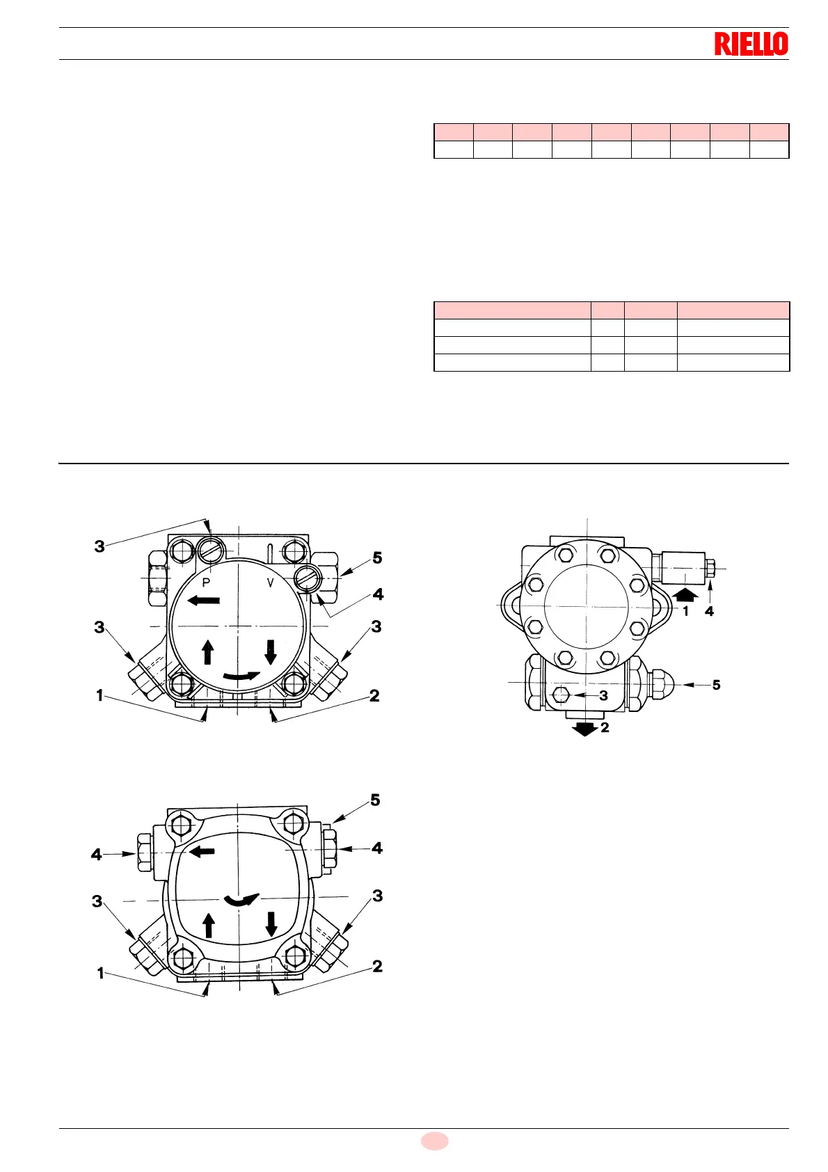
Fig. 20
PRESS GW
D376
SUNTEC ANV67
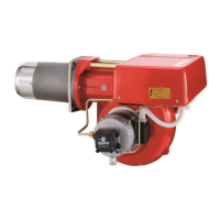
Fig. 21
PRESS 1G - 2G
D377
SUNTEC ANV 77
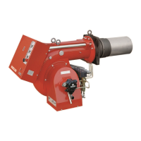
Pump ANV J
- Suction G 1/4" G 1/2”
- Return G 1/8" G 1/4”
- Pressure gauge attach. G 1/8" G 1/8”
- Vacuummeter attachment G 1/8" G 1/2”
- Pressure adjustment screw:
Right rotation = pressure increases
Left rotation = pressure decreases
Fig. 22
PRESS 3G
D378
SUNTEC J6