20140894
28
Electrical system
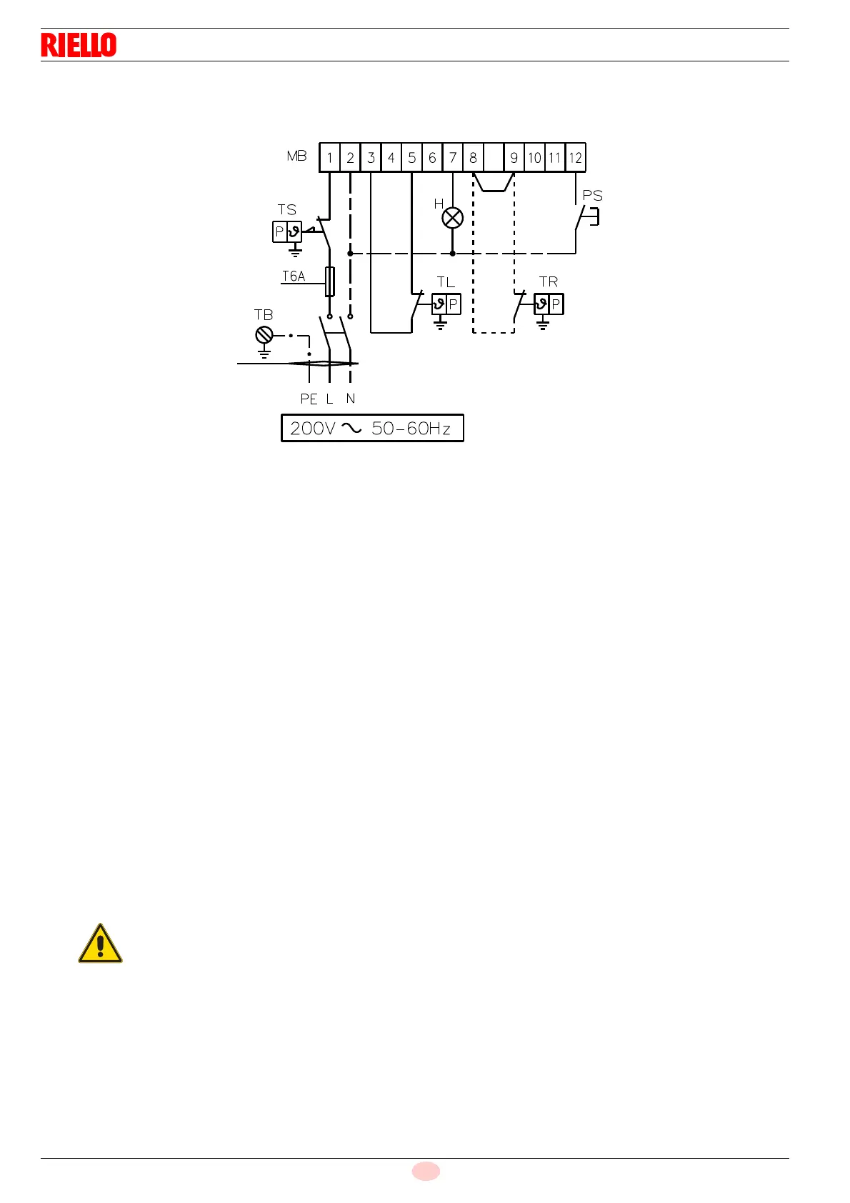
6.2.3 PRESS GW electrical connection of burner (single-phase model)
(by installer)
Key (Fig. 25):
IN - Manual burner stop switch
MB- Burner terminal strip
PS- Lock-out reset button
S - Remote lock-out signal
TB- Burner ground (earth) connection
TL- Limit control device system:
This shuts down the burner when the boiler temperature or
pressure exceeds the setpoint value.
TR- High-low mode control device system:
This controls operating stages 1 and 2 and is necessary
only for two-stage operation.
TS- Safety control device system:
This operates when TL is faulty.
the burner is delivered preset for single-stage operation with
a jumper inserted in the terminal strip, see (Fig. 27 at page 29).
If two-stage operation is required, remove the jumper between
terminals 10-11 and insert the control device TR in its place to
command the 2nd gas oil solenoid valve.
These models leave the factory preset for 200V power supply
50Hz.
– Do not invert the neutral with the phase wire
in the electricity supply line. Any inversion
would cause a lockout due to firing failure.
– Only use original spare parts to replace the
components.