15
20140894
Installation
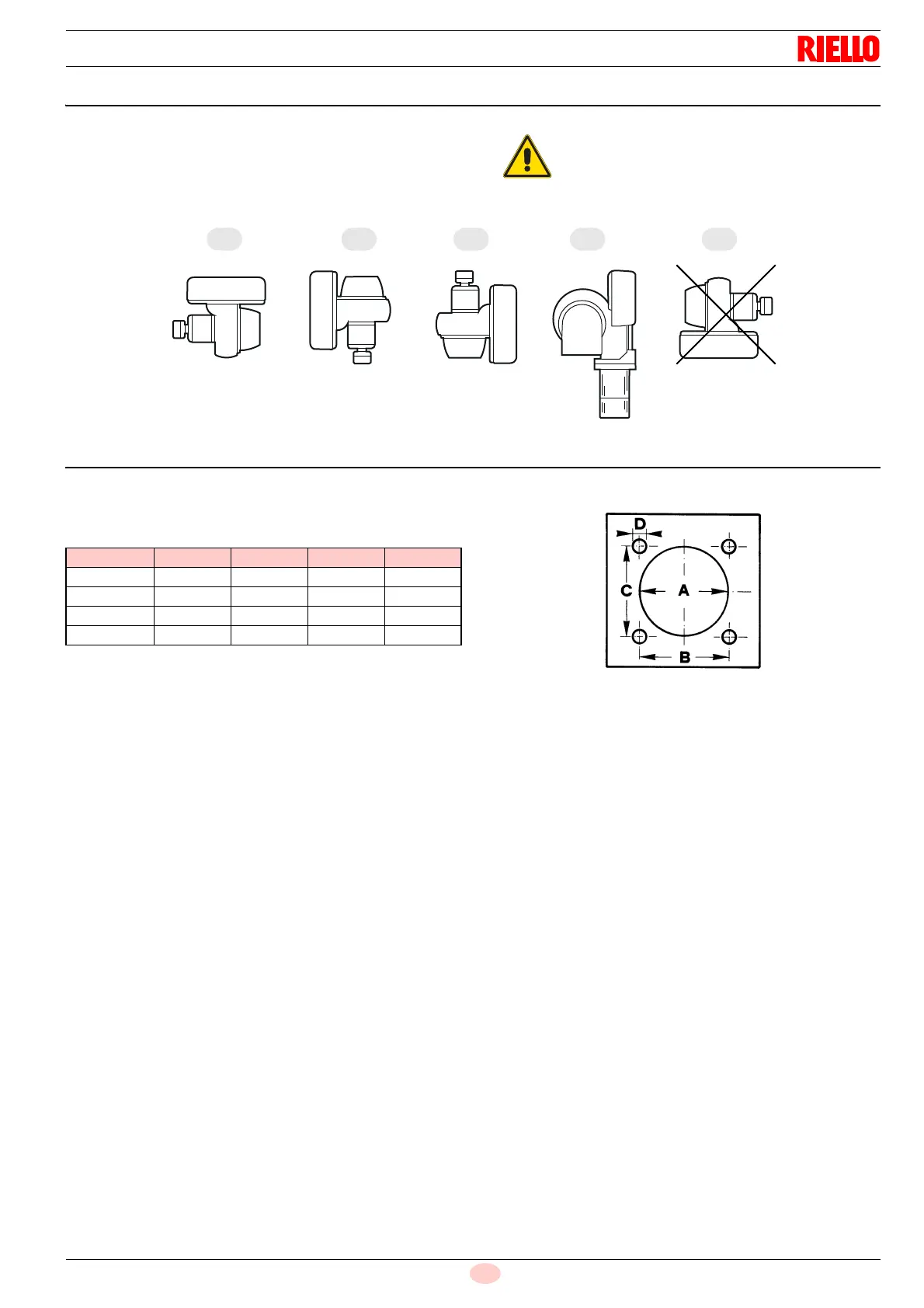
5.4 Operating position
The burner is designed to work only in the positions 1, 2, 3 and 4.
Installation 1 is preferable, as it is the only one that allows per-
forming maintenance operations as described in this manual.
Installations 2, 3 and 4 permit operation but make maintenance
and inspection of the combustion head difficult, page 37.
5.5 Boiler plate
Drill the combustion chamber locking plate as shown in Fig. 10.
The position of the threaded holes can be marked using the ther-
mal screen supplied with the burner.
Tab. E
Any other position could compromise the correct
working of the appliance.
Installation 5 is prohibited for safety reasons.
mm A B C D
PRESS GW 155 160 160 M10
PRESS 1G 165 160 160 M10
PRESS 2G 165 160 160 M10
PRESS 3G 185 195 195 M12