21
20140894
Installation
Useful suggestions for both systems (A) and (B):
– Use copper pipes whenever possible.
– Any curves used in the system should be made with the wid-
est possible radius.
– Use biconic connectors at both ends of the pipe.
– Whenever the burner is installed in areas with extremely cold
winter climates (temperatures lower than -10°C), we recom-
mend insulating both the tank and the piping. Avoid the small-
est of the three pipe diameters provided in the Table and lay
the piping along the most sheltered route possible. The par-
affin in the fuel begins to solidify below 0°C, and the filters
and nozzle begin to clog accordingly.
– Install a filter on the suction lines with a transparent plastic
bowl if possible in order to permit the regular flow of fuel and
quick checking of the state of the filter.
– The return pipe does not require an on/off valve, but if the
user desires to insert one, a lever-type valve should be se-
lected which clearly indicates when the valve is open or
closed (if the burner starts with the return pipe closed, the
sealing organ located on the pump shaft will break).
– The opening of the burner or the boiler door must not twist the
flexible hoses that connect the copper pipes to the pump.
– If more than one burner is operating in the same room, each
one must be equipped with its own suction pipe; the return
pipe may be shared by all, providing it is sufficiently sized.
– The suction line must be perfectly airtight. In order to check
the seal, close the pump's return line. Install a union T on the
vacuum meter attachment. On one branch of this T install a
pressure gauge and on the other branch inject air at a pres-
sure of 1 bar. After the air injection, the gauge must remain at
a constant pressure.
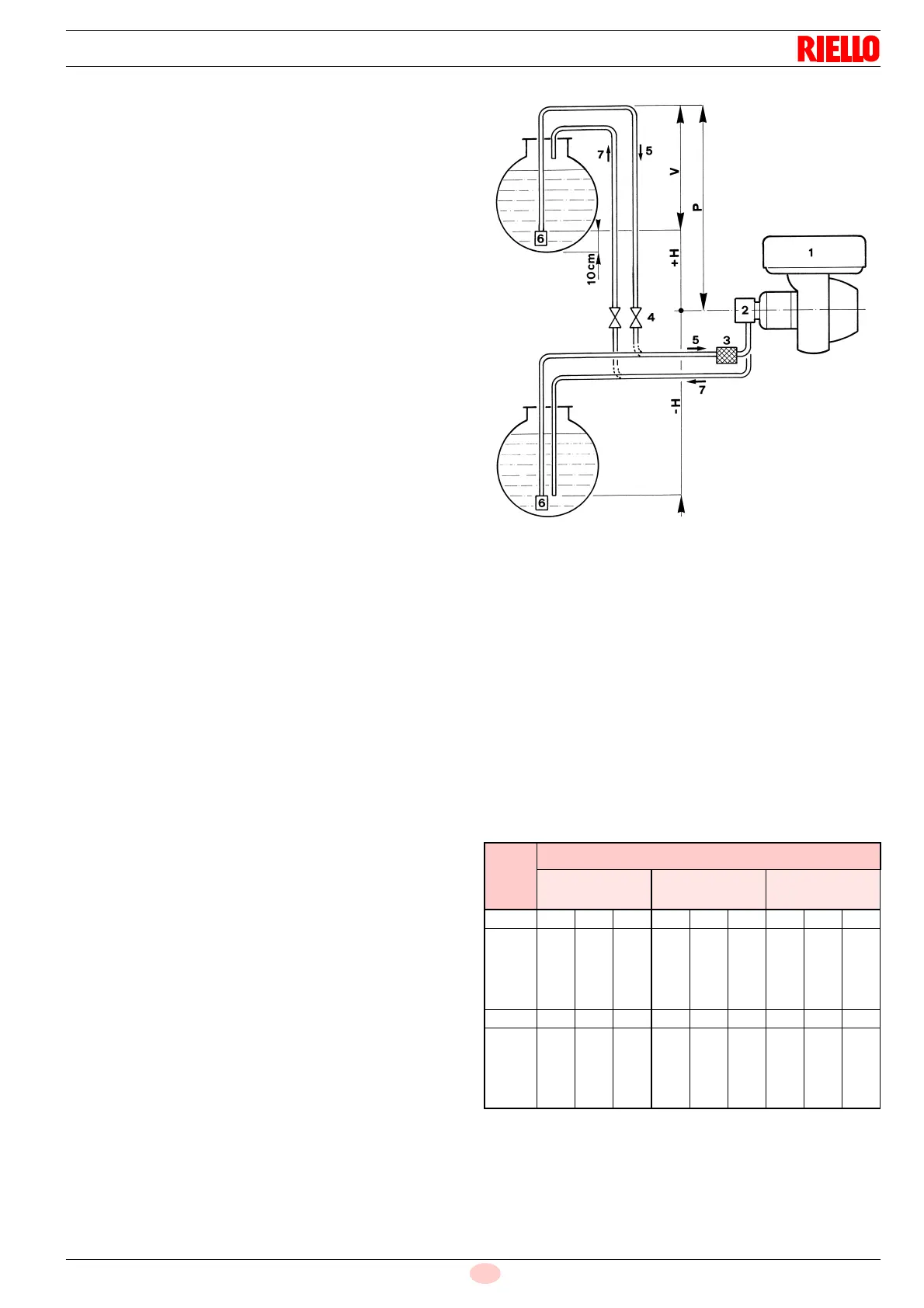
Key (Fig. 17)
H Pump/Foot valve height difference
L Piping length
• values calculated for gas oil:
• viscosity = 6 cSt/20°C
• density = 0.84 kg/dm
3
• temperature = 0°C
• max altitude = 200 m (a.s.l.)
ø Inside pipe diameter
1Burner
2Pump
3 Filter
4 Manual on/off valve
5 Suction line
6 Foot valve
7 Return line
Tab. H
+H
-H
m
L m
PRESS GW
Ø mm
PRESS 1G - 2G
Ø mm
PRESS 3G
Ø mm
8 1012101214121416
+4
+3
+2
+1
+0,5
35
30
26
21
19
90
80
69
59
53
152
152
152
130
119
63
55
48
40
37
144
127
111
94
86
150
150
150
150
150
71
62
53
45
40
139
123
106
90
82
151
151
151
151
151
0 17 48 108 33 78 150 36 74 137
-0,5
-1
-2
-3
-4
15
13
9
4
-
43
37
27
16
6
97
86
64
42
20
29
25
17
10
-
70
62
45
29
12
133
118
88
58
28
32
28
19
10
-
66
58
42
26
10
123
109
81
53
25