Chapter 8 Protocol Decoding RIGOL
MSO1000Z/DS1000Z User’s Guide 8-15
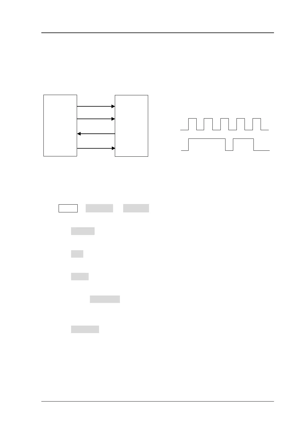
SPI Decoding (Option)
SPI bus is based on the master-slave configuration and usually consists of chip select
line (CS), clock line (SCLK) and data line (SDA). Wherein, the data line includes MISO
and MOSI.
Master
Slave
MOSI
SCLK
MISO
CS
Figure 8-1 SPI Serial Bus
SCLK: SDA is sampled on the rising or falling edge of clock.
SDA: represents the data channel.
Press MATH Decode1 Decoder to select “SPI” and open SPI decoding
function menu.
1. Press Decode to turn on or off the decoding function.
2. CLK Setting
Press CLK to select any channel (CH1-CH4 or D0-D15) as the clock channel.
3. MISO and MOSI Settings
Press MISO to select any channel (CH1-CH4 or D0-D15) as the MISO data
channel. If “OFF” is selected, this data line is not set. You can use the same
method to set the MOSI data line.
Note: Press Exchange to switch the current signal sources of the clock channel
and data channel.
4. Copy Trigger
Press CopyTrig to copy the protocol trigger settings from the trigger system
and set the corresponding decoding parameters automatically. During SPI
decoding, this function is valid only when the trigger type is SPI trigger. You can
copy the settings of clock, data channel, databits, edge, type (CS/Timeout), CS
channel, CS polarity and timeout time as well as set the data polarity to positive.
 Loading...