KBD Series Manual 31
The following informaon should be used in conjuncon
with the IPEX System 636 Installaon Guide:
Terminaon kits are to be tested and cered for use
with the brand of pipe-ng-cement system that is to
be ulized in the applicaon. The IPEX Low Prole
terminaon is fully cered for use with IPEX product
only.
System 636 PVC Low Prole Vent kits are rated to 65°C
maximum and are made from cered compound.
All terminaon kits must be located and installed in
accordance with these instrucons, local building code,
and CSA B149.1 Natural Gas and Propane Installaon
Code.
All exhaust vents and air inlets must terminate at the same
height to avoid property damage, personal injury, or death.
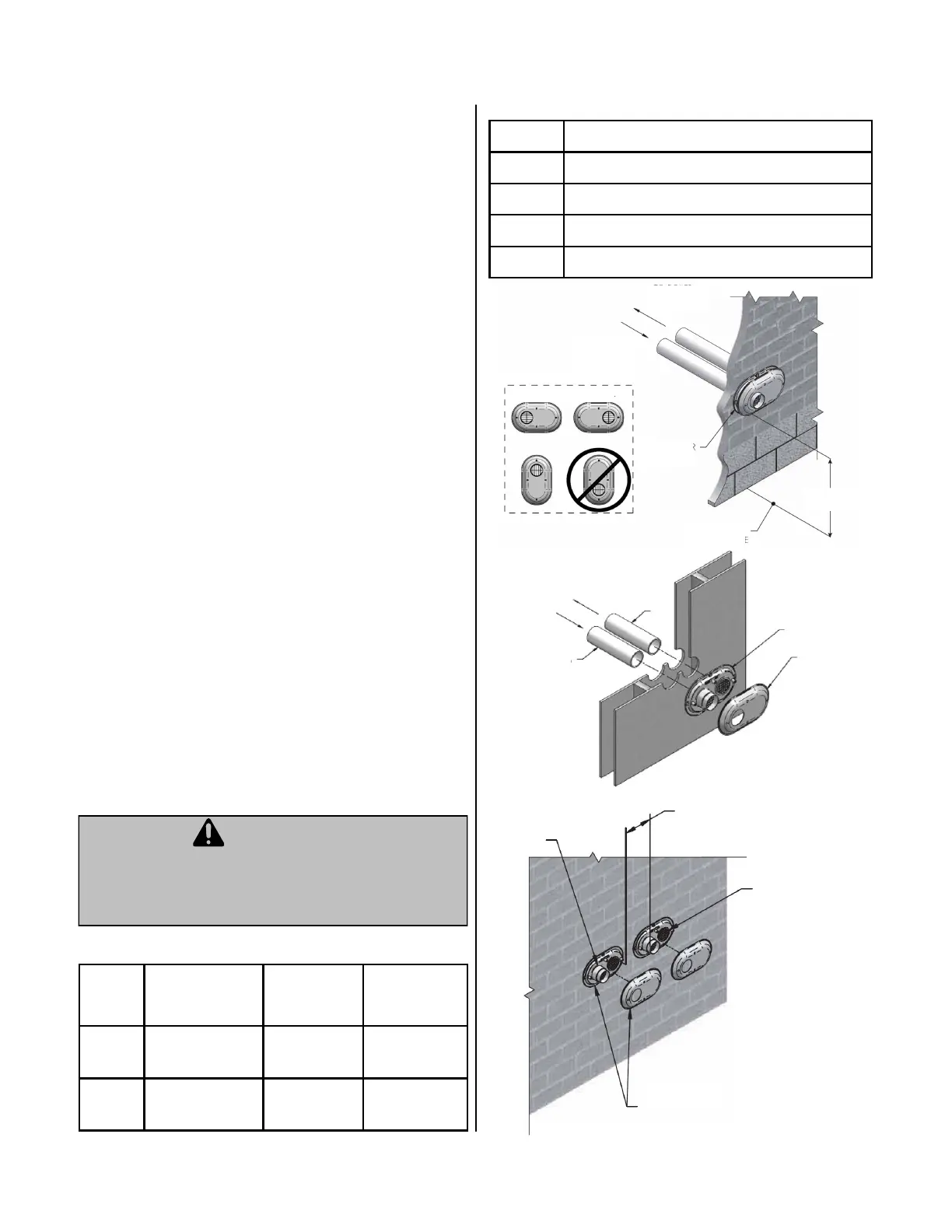
Cered PVC/CPVC Vent Terminaon Opons (connued)
1. Once a proper locaon has been determined, cut 2
appropriately sized holes in the wall to accommodate
the pipe. (Reference the Low Prole Terminaon
Kit-Dimensions table below)
2. Slide intake and exhaust pipes through the holes.
Secure (using solvent cement) both pipes to the base
of the vent terminaon kit. (Be sure to follow
guidelines for solvent cemenng as described in the
System 696 Installaon Guide)
3. Use the supplied screws and anchors to secure the
base to the wall. (a drilled 3/16” hole, 1-3/16” deep
will be needed for the anchors.) Use the base as a
template to locate the anchor hole.
4. Using the supplied screws, secure the Cap to the Base.
5. Upon securing the vent terminaon and pipes, seal the
wall penetraons (from the interior) using a PVC
compable sealant material.
Item # Descripon Pipe Outside
Diameter
Hole Spacing
(Ctr to Ctr)
196985
3” Flush Mount
Vent Kit
3.5” 5.6”
196986
4” Flush Mount
Vent Kit
4.5” 5.6”
-
Qty Item Descripon
1 Base (Two Holes)
1 Cap (One Hole)
8 Stainless Steel Screws
4 Plasc Anchors
Air Piping
Vent Piping
Vent Base
Vent Cap
Vent
Air
Vent / Air
Terminaon
12” Min Between Edge of Air
Inlet and Adjacent Vent Outlet
From Water Heater Vent
Pipe Connecon
To Water Heater Intake Air
Connecon
12” min
Vent / Air
Terminaon
Orientaons
Grade or
Snow Line
 Loading...