Rittal roof-mounted Blue e+ cooling unit/VX25 Blue e+ integration solution 31
7 Operation
EN
Change unit
All temperature values for the unit may be displayed ei-
ther in degrees Celsius "°C" or degrees Fahrenheit "°F".
Click on the "Change unit" symbol.
Change the required unit ("°C" or "°F") using the "Up"
or "Down" arrows.
Confirm your entry with "OK".
Control mode
The cooling unit controls cooling output according to
one of the following three temperature values:
– Inside temp.: The temperature at which air is drawn
out of the enclosure into the cooling unit.
– External sensor: The temperature measured with an
external temperature sensor at a so-called hot spot in
the enclosure.
– Outlet temp.: The temperature measured with an ex-
ternal temperature sensor at the cold air outlet from
the cooling unit.
Control mode "external sensor"
Please observe the following when selecting the sensor
position: The sensor must not
– be influenced directly by the cold air expelled from the
cooling unit,
– be influenced by external heat sources or heat radia-
tion,
– be exposed to humidity,
– have its connection cable laid in the vicinity of AC ca-
bles,
– be exposed to different temperature levels within the
first 10 cm of the connection cable.
The sensor must
– be located within the effective range of the cooling
unit,
– be surrounded by adequate moving air which has
blended well with the air expelled by the cooling unit,
– be at an adequate distance from solid and liquid sub-
stances.
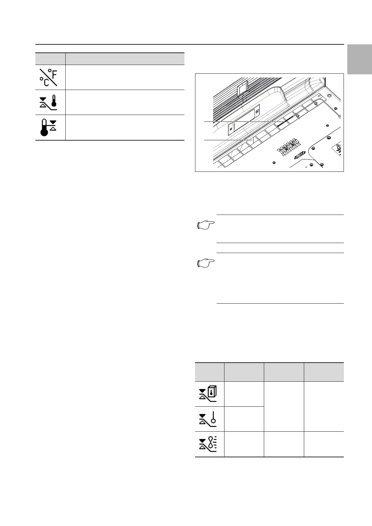
Control mode "outlet temperature"
Attach the temperature sensor in front of the cold air
outlet from the cooling unit, in the centre (fig. 20).
Fig. 20: Temperature sensor in front of cold air outlet
Key
1 Temperature sensor
2 Cold air discharge at the bottom of the unit
Selecting a control mode
Click on the "Control mode" symbol.
The setpoint for the currently set control mode is dis-
played.
Choose your preferred control mode by selecting it
from the display:
The corresponding symbol for the chosen control mode
is likewise displayed on the overview page.
Symbol Parameter
Change unit
Set the unit "°C" or "°F"
Control mode
Alarm threshold
Temperature limit which will trigger an alarm
message if exceeded.
Tab. 13: "Temperature" zone
Note:
The sensor element must not be in contact
with the enclosure.
Note:
To ensure the accuracy of the outlet temper-
ature, at least 50% of the total cooling output
should be installed as heat loss. The output
can be taken from the characteristic curve for
this unit.
Symbol Parameter Setpoint Factory
setting
Internal
temperature
20 °C (68 °F)
…
50 °C
(122 °F)
35 °C (95 °F)
External
sensor
Outlet
temperature
18 °C (64 °F)
…
28 °C (82 °F)
24 °C (75 °F)
Tab. 14: "Control mode" zone
1
2