3
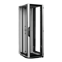
Schranksystem VX IT / VX IT enclosure system / Baies VX IT
Contents
Page
1. Notes on documentation 6
1.1 Declarations of conformity
and approvals 6
1.2 Storing the documents 6
1.3 Symbols used 6
1.4 Other applicable documents 6
1.5 Normative references 6
1.6 Country-specifi c references 6
2. Safety instructions 7 – 37
2.1 Intended use 7 – 29
2.2 User groups to
IEC 62 368 7–29
2.3 Safety instructions 7 – 29
– Explanation of
safety symbols 30 – 37
3. Device description 38 – 42
3.1 Function description
and components 38
3.2 Labelling 39
3.3 Scope of delivery 40 – 42
4. Assembly and siting 43 – 67
4.1 Site requirements 43
4.2 Required tools 43
4.3 Assembly procedure 44 – 67
4.3.1 Releasing the packing bands
and unpacking 44
4.3.2 Reading the instructions 44
4.3.3 Removing the
enclosure panels 45 – 48
– Dismantling the
aluminium front doors 45
– Dismantling the rear doors 46
– Dismantling the rear panel 47
– Dismantling the side panels 48
Page
4.3.4 Removing any accessories
supplied loose 49
4.3.5 Lifting the rack o of the pallet 49
4.3.6 Removing the cardboard
from the bottom 50
– Optional installation of
the base/plinth 50
– Installing castors or
levelling feet 51
4.3.7 Moving the rack to
the installation site 52
4.3.8 Preparing for installation 53 – 64
– Depth adjustment of the
482.6 mm (19˝) level 54 – 59
– Width adjustment of the
482.6 mm (19˝) level 60 – 62
– Moving the swing frame 63
– Swing frame –
Swapping the hinges 64
4.3.9 Baying the rack (optional) 65
4.3.10 Securing the rack to the fl oor 66
4.3.11 Installing/modifying
gland plates (optional) 67
5. Transport 68
6. Installation 69 – 91
6.1 Installing the
customer hardware 69 – 77
6.2
Installing the power and
network cables 78 – 82
– Cable entry in the roof 78
– Dismantling/assembling of
the roof plate (optional) 79
– Venting the roof plate (optional) 80
– Cable entry in the base 81
– Cable management
accessories 82
6.3 Connection points,
protective earthing, electrical
safety, accessory kits for
protective earthing 83 – 84
Page
6.4 Re-installing the removed
enclosure panels 85 – 91
– Fitting the rear doors 85
– Fitting the rear panel 86
– Fitting the side panels 86
– Fitting the aluminium front door –
r/h door hinge 87
– Fitting the aluminium front door –
l/h door hinge (swapping hinge
to opposite side) 88 – 89
– Fitting the sheet steel door –
l/h door hinge (swapping hinge
to opposite side) 90
6.5 Other accessories 91
7. Commissioning 92
8. Operation 92 – 93
9. Troubleshooting 93
10. Inspection and maintenance 94
11. Storage and disposal 94
12. Technical
specifi cations 95–102
– 482.6 mm (19˝) mounting
angles, standard 95 – 97
– 482.6 mm (19˝) mounting
angles, dynamic 98 – 100
– Empty enclosure 101
13. Spare parts 103
14. Warranty 103
15. Customer services addresses 103