M3
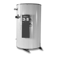
CONDENSING WATER BOILER
27
34-1115 12/15
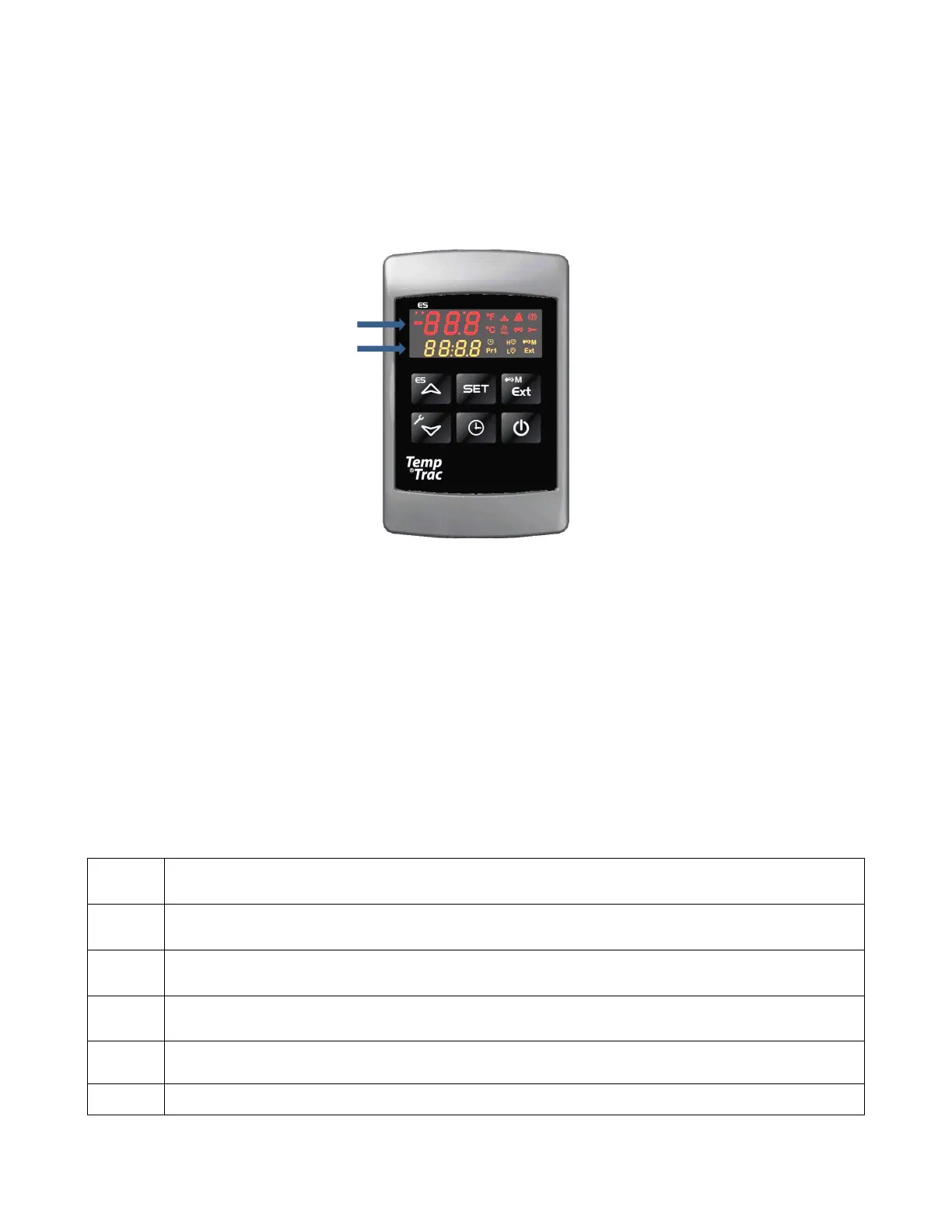
10 TEMPTRAC™ Electronic Controller Panel
10.1 Principle Of Operation
The boiler operates to satisfy the setpoint of the TempTrac digital control whose operating sensor is located near the
top of the boiler tank, or in the return line of a Hydronic system, depending on the application. Demand (flow) will
typically create a drop in temperature, thus activating the boiler to add heat to the hot water supply. This setpoint is
the desired boiler water temperature to maintain, as measured at the operating sensor location.
10.2 Upper LED Readout
The upper readout is normally configured to display the monitoring probe (TP2) temperature reading.
This readout can display additional information by pushing the EXT button to cycle through the following items:
• The temperature reading from (probe TP3), which is located in the vent connection and monitors the flue gas
temperature (if equipped).
• The modulating range of the burner, indicated by 0 to 100%.
• The temperature difference between TP1 and TP2.
All of the display information described above is available for monitoring through the optional MODBUS RTU
interface.
10.3 Lower LED Readout
The lower readout is normally configured to display the control sensor (TP1) temperature reading.
10.4 Control Buttons
SET
Displays and modifies the temperature set points.
In programming mode, it selects a parameter or confirms an operation.
UP
Displays and modifies the energy saving (Night Time setback) settings.
In programming mode, it browses the parameter codes or increases a displayed value.
DOWN
Displays the working hours of the load relays.
In programming mode, it browses the parameter codes or decreases a displayed value.
CLOCK
Changes lower display from the stored water temperature to current time and day.
EXT
Changes upper display to show the temperature at Probe TP1, TP2 or TP3, the percent of the
modulating range or the temperature at Probe TP1 minus the temperature at Probe TP2.
ON/OFF
Switches the control ON or OFF.
(See TempTrac User Manual 34-80 for full description)
UPPER LED READOUT
LOWER LED READOUT