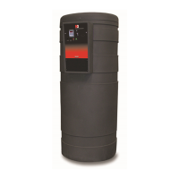
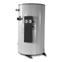
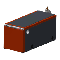
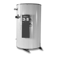
M3
CONDENSING WATER BOILER
31
34-1115 12/15
L1-L2: Used for incoming 120VAC power supply connection. Terminal L1 is the HOT terminal and L2 is NEUTRAL.
See the product catalog or specification document for circuit ampacity rating.
R1-R2: Used to activate / de-activate boiler from remote master control. When switching this low current circuit, a
relay with gold plated contacts or the use of two relay contacts in parallel must be used. Terminals are wired to a
relay in a remote Energy Management System. When the relay closes, the circuit from R1 to R2 is completed and
appliance controls are enabled. This appliance ships from factory with a jumper between terminals Remove jumper
when connecting to a remote controller. The indication of this function is described in section 10.8 LED Display
Alarm Messages.
A1-A2: Used to activate a remote alarm, signaling shutdown of combustion control. Provides a maximum 3 amp
relay contact closure when the flame safeguard terminates combustion due to a tripped safety interlock (i.e.: air
proving switch, high limit switch or flame sensor, etc.).
P1-P2: Provides a low amperage dry contact to control remote equipment (i.e. mechanical room air louvers, draft
inducer or power vent, etc.). Do not directly energize pumps or motors through these terminals. If operation or
repositioning of the remote equipment is required for safe operation of the appliance, the remote equipment must
send a return proving signal to terminals C1-C2, via its proving switch, to confirm proper operation or repositioning to
enable the appliance to energize.
C1-C2: Used for proving operation of remote equipment. Terminals are wired to a proving switch on a remote device
such as an isolation valve, primary pump, a power venter, louvers, or a combination of these in series. When all
remote proving switches close, the circuit from C1 to C2 is completed and the appliance controls are enabled. This
appliance ships from the factory with a jumper between terminals C1 and C2 that must be removed when a proving
switch is connected.
11.3 Connecting Isolation Valves
Motorized isolation valves can be controlled by the building automation system or through an OnTrac
®
boiler
management system. If an OnTrac
®
boiler management system is used, the motorized isolation valve must be
energized by a field provided isolation relay connected to the low amperage terminals (CIRCULATOR 1-2) located
on the terminal strip shown in the pictorial drawing in section 16.3 “Component Wiring and Conduit Routing Details.”
Do not energize an isolation valve connected directly to these low amperage terminals. These terminals are not for
use with a circulator pump.
12 SEQUENCE OF OPERATION
1. Incoming 120VAC
a. Full time power to the Fuse.
b. Full time power to the Main Control Switch.
2. Power On - When the main control switch is turned on:
a. 120V is applied to the step-down transformer (24V).
b. 120V is applied to the L.W.C.O. terminal L1 (if used).
c. 120V is applied to the Fenwal Flame Ignition Control.
d. 24V is applied to the TempTrac operating temperature control terminal L1.
e. Full time power to the Variable Frequency Drive.
3. Control Device Pre-check – Power flows through the following control devices before reaching call-for-heat
control. The following devices are listed in circuit order:
a. The Electronic Low Water Cut-Off control when installed is the first device in the control circuit.
b. The High Gas Pressure and Low Gas Pressure Switch are energized and their monitored pressures are
proved.
c. The High Temperature Limits are energized.
d. Terminals P1-P2 terminals close to activate a pump, if used, or to activate any connected remote devices.
e. The circuit between Terminals C1-C2 is closed by the jumper or by any connected remote proving switches,
enabling the boiler to continue the sequence of operation (C1-C2, see Section 11.2).
f. Isolation valve terminals are energized.