M3
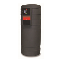
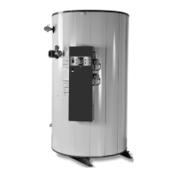
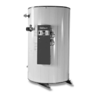
CONDENSING WATER BOILER
32
34-1115 12/15
4. Call For Heat - If the TempTrac operating control senses a call-for-heat condition and the previous safety
devices are energized the following sequence will begin:
a. The enable contacts for the VFD are energized for the modulating burner models or the blower contacts
close for the fixed input burner models.
b. The Airflow-Proving Switch then proves the operation of the burner blower.
c. The thermostat contact on the Fenwal Flame Ignition Control is energized.
5. Heat-Up - Following the pre-purge delay, the hot surface igniter will be energized:
a. The flame control will send 120V to the hot surface igniter for 20 seconds.
6. Ignition - When dwell time is completed a 4-second Trial for Ignition (TFI) period is initiated:
a. The Delay-On (Low Fire Hold) Relay and the Gas Safety Valves are energized.
b. During TFI the flame safeguard control will monitor the flame using flame rectification through the hot
surface igniter.
c. If the flame control senses the presence of flame before the end of the TFI period, the igniter will be de-
energized and the flame control will continue to monitor the flame, through the igniter, until the operating
thermostat ends the call for heat condition.
7. Modulation Release - Once the Delay-On (Low Fire Hold) relay has timed out, the TempTrac will regulate the
speed of the blower through the VFD.
a. The TempTrac will continue to monitor the water temperature in the boiler.
b. When the setpoint temperature is reached, the call-for-heat signal to the flame safeguard control is
discontinued. When the call for heat condition ends, the gas valve will close and the burner will end
operation.
c. The VFD will ramp the blower speed down and stop after 10 seconds.
d. As the water temperature in the loop drops below setpoint, the TempTrac will sense this condition and
begin the call-for-heat sequence again.
8. Loss of Flame Signal
If the hot surface igniter fails to sense flame during an attempt to light the burner (trial for ignition), the ignition
control will lockout. However, if the hot surface igniter fails to sense the flame at any time during normal burner
operation (flame failure), the gas valve will be closed and another call for-for-heat sequence will be initiated to
attempt to relight the burner. If this attempt to relight the burner and sense flame fails (single retry), the ignition
control will shut-down and lockout. The blower will complete post-purge operation to exhaust any remaining
combustion products until the call for heat ends.
9. Alarm on Any Failure
a. When any safety device or remote proving interlock prevents the burner from firing within the allotted time
period once the call-for-heat is initiated (approx. 7 minutes), the TempTrac will initiate an alarm notification.
This notification is indicated in the following ways:
• A flashing alarm message “AL2” is displayed on the TempTrac screen.
• A high pitch beeping audible alarm.
• The dry contacts at terminals A1 & A2 will close. 3 amp max load.
• The alarm register, accessible through the Modbus RTU communication option, shows alarm.
b. To reset the TempTrac once the alarm is activated, attempt to determine the safety device which caused
the condition and correct the condition. Once the condition is corrected, the TempTrac can be reset by
pressing any button. If the lockout is caused by the ignition control, power must be re-cycled in order to
reset the ignition module.
c. See the troubleshooting guide, Section 15 of this manual, for more details.