M3
CONDENSING WATER BOILER
30
34-1115 12/15
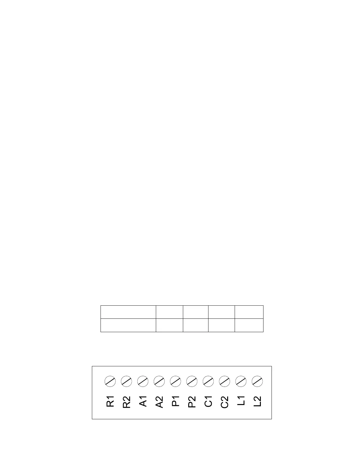
11 REMOTE CONNECTIONS – TERMINAL STRIP
11.1 Making BMS/BAS remote connections for analog and binary (on/off) signals
A terminal strip for the remote connection is located behind the bottom control panel door and is accessed removing
the four thumb screws a lifting the hinged door.
WARNING: Turn off all electrical service to the appliance when accessing the remote connection terminal
strip located inside the bottom control panel door and close and fasten bottom control panel door before
restoring electrical service to the appliance. The control panel contains High Voltage wiring and terminals. If
the electrical service is not turned off and these terminals are touched, a dangerous shock could occur,
causing personal injury or death.
Coupez l'alimentation avant intervention sur l'appareil.
1. If BMS/BAS provides remote on/off control directly to each boiler but allows boiler to control
modulation on its own:
• Remove the jumper connecting terminals R1 and R2.
• Connect the BMS output leads for the enable/disable function to terminals R1 and R2.
• Leave all other wires in their initial positions.
2. BAS connection over network with MODBUS RTU protocol (requires option ALMMB)
• An optional serial connection cable (part no. 106624) enables the TempTrac to communicate via Modbus
RTU to a Building Automation System or to the OnTrac
®
multiple boiler control. Connections are made using
shielded, twisted pair wiring in a daisy chain arrangement.
3. BAS Protocol Gateways
When communicating over a network connection, the standard protocol of the TempTrac control is Modbus
RTU. The standard protocol between the OnTrac and the BAS is Modbus TCP/IP. A gateway will be required to
communicate with the BAS if it uses a different protocol. Riverside Hydronics
®
offers pre-mapped gateways that
support BACnet MSTP, BACnet IP, Lonworks or Johnson Controls N2. Consult factory for other protocols. (For
a general overview of the application of this gateway, refer to Setup Manual #34-525.)
These third-party supplied gateways are custom-programmed components that must be sourced through
Riverside Hydronics
®
.
IMPORTANT: Do not use single strand bell wire for remote field connections to terminals R1-R2 and C1-C2. Use
only multi-strand copper wire. See table below for wire length and gauge:
11.2 Terminal Functions - The following describes the functions of each of these terminals and the proper
method for interfacing with an Energy Management System:
Wire Gauge 18 GA 16GA 14 GA 12 GA
Maximum Length 30 FT 50 FT 75 FT 100 FT