M3
CONDENSING WATER BOILER
29
34-1115 12/15
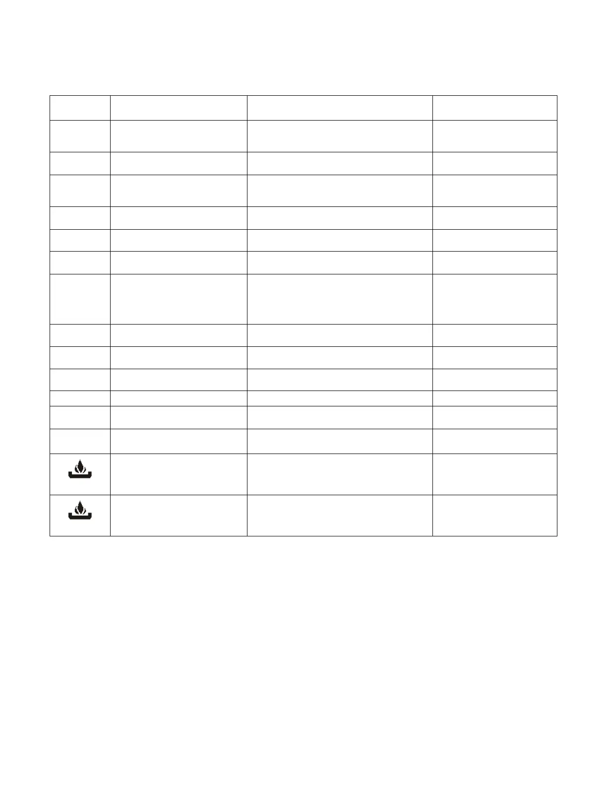
10.9 LED Display Alarm Messages
Alarm messages are displayed in the upper LED readout and alternate with the default display. An alarm LED ICONs
also illuminated.
ALARM
MESSAGE
CAUSE RESULTS OF ALARM CONDITION
RECOMMENDED
ACTION
“P1” TP1 probe failure
Return temperature sensor is not connected or is
reading incorrectly. Call for heat and burner
modulation output signal will revert to low fire.
Check wiring and sensor
Terminals 14 & 17
“P2” TP2 probe failure
Temperature sensor is not connected or is
reading incorrectly.
Check wiring and sensor
Terminals 15 & 17
“P3” TP3 probe failure
Temperature sensor is not connected or is
reading incorrectly or flue gas temperature
protection is disabled.
Check wiring and sensor
Terminals 16 & 17
“HA”
High temperature limit setpoint
exceeded
Audible alarm sounds, operation continues. Manual reset required
“LA” Low temperature alarm Audible alarm sounds, operation continues.
AL1 Digital input 1 is activated.
Unit de-energized after timer delay. Audible
alarm sounds.
Manually reset required
AL2
Digital input 2 is activated.
This alarm indication is dedicated to
the Alarm On Any Failure feature of
this product.
Unit de-energized after timer delay. Audible
alarm sounds. Alarm contacts close for remote
indication of alarm. Internal alarm register will
communicate an alarm condition though the
Modbus RTU communication link.
Manually reset required
AL3 Digital input 3 is activated.
Unit de-energized after timer delay. Audible
alarm sounds.
Mn1 Maintenance alarm for output 1 Buzzer sounds, operation continues Check wiring and sensor
Mn2 Maintenance alarm for output 2 Buzzer sounds, operation continues Check wiring and sensor
Mn3 Maintenance alarm for output 3 Buzzer sounds, operation continues Check wiring and sensor
“rtc”
The real time clock has lost its
setting
Energy saving function disabled Reprogram clock
CONTROL
MESSAGE
CAUSE RESULTS OF CONTROL CONDITION NOTES
On
A call-for-heat condition The burner operating sequence should begin.
If the burner does not operate,
check safety devices or Remote
Proving Interlock
Flashing
The remote enable/disable has
been triggered
The small flame icon will flash indicating the
standby state
The R1-R2 terminals have been
opened by the remote master
control. The boiler will remain in
standby.