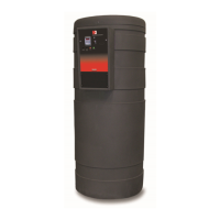
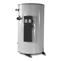
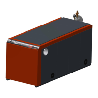
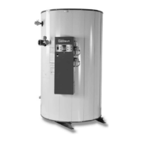
M3
CONDENSING WATER BOILER
35
34-1115 12/15
16. If the TempTrac operating control switch is closed (indicated by the
icon), the burner blower should come on
and pre-purge begins.
17. If nothing happens, check for a safety device lockout. Some safety devices such as the Low Water Cut-off, Gas
Pressure Switches and the High Temperature limit will require manual reset after lockout and therefore can be
easily identified.
18. When the blower motor starts, the Flame Ignition Control will not be energized until positive air flow is
established and the Remote Proving Interlock, when used, has closed. If the Flame Ignition Control does not
energize, see the troubleshooting guide for help.
19. The Air Proving Switch can be easily identified by checking for 120V on both sides of the switch.
20. If the amber colored call-for-heat indicating light is not illuminated, it is likely that the Remote proving interlock is
open. Check remote device.
21. After the pre-purge, the flame control energizes the HSI for the heat up period, approximately 20 seconds. At
the end of that period the gas valve is opened for approximately 4 seconds. After the burner lights and the
primary safety control senses a flame, the burner will remain on until the call for heat is satisfied or operation is
interrupted by a safety device.
22. If the burner fails to light, the flame control will lockout. When lockout occurs, cycle the main power switch to
reset the flame ignition control before the alarm-on-any-failure occurs. When the burner fails to ignite, the most
common cause at startup is air in the gas supply. This can usually be corrected with multiple cycles or bleeding
the line manually. If the burner lights but blows out, ensure that the burner firing rate is locked in low fire and
check for improper combustion or weak flame signal as a possible cause.
23. Once the main burner flame is established the firing rate will be controlled by the TempTrac control.
24. Burner Combustion Adjustment
CAUTION: Use a combustion analyzer to adjust combustion. Do not attempt to adjust the burner by sound or
sight. With the burner firing, insert the combustion analyzer probe in the flue vent approximately two feet from
the appliance. All models are adjusted as follows:
With the burner firing and adjusted to Low Fire, adjust the regulator screw clockwise (counter clockwise for the
400, requires Allen wrench) to increase gas flow or counter clockwise to decrease flow. The desired CO
2
in the
combustion products must be between 8.5 and 9.5% for natural gas, 9.5% to 10.5% for LP gas. Do not attempt
to adjust combustion based on manifold pressure alone. Manifold pressure should only be used as a reference
point. It should not be necessary to adjust the regulator for these models. See Gas Train Illustrations for
details.
a. Once the desired combustion is achieved at Low Fire, raise the burner firing rate to High Fire. Adjust the
valve orifice clockwise to reduce the flow of gas and counter-clockwise to increase the flow of gas in order
to maintain the desired CO
2
in the combustion products between 8.5 and 9.5% for natural gas, 9.5% to
10.5% for LP gas.
b. When High Fire combustion has been reached and combustion is within the proper range, return to low fire
to confirm settings again.
c. If at any point of the modulation range, the carbon monoxide level is in excess of 200ppm and cannot be
successfully adjusted below that level, contact RIVERSIDE HYDRONICS
®
customer service for assistance.
WARNING: Do not continue to operate the appliance with carbon monoxide levels above 200 ppm.
Carbon monoxide is a colorless, odorless and poisonous gas that commonly results from gas
combustion. High concentrations of Carbon Monoxide are extremely dangerous to humans and
animals. Operation of an appliance at carbon monoxide levels above 200ppm can cause unsafe
operation and the potential for poisonous carbon monoxide to enter occupied areas. Such improper
installation can cause property damage, personal injury, exposure to hazardous materials or death.
d. Close and seal the opening in the vent through which the combustion analyzer probe was inserted. Use a
plug or seal with heavy adhesive backed aluminum tape with an adhesive suitable for the vent temperatures
expected inside the selected and installed vent system and for condensing conditions.
25. Return the PS4 modulation parameter value to nu for automatic operation.
26. Enable or reconnect any BMS/BAS control interface removed prior to the setup and adjustment of each boiler.