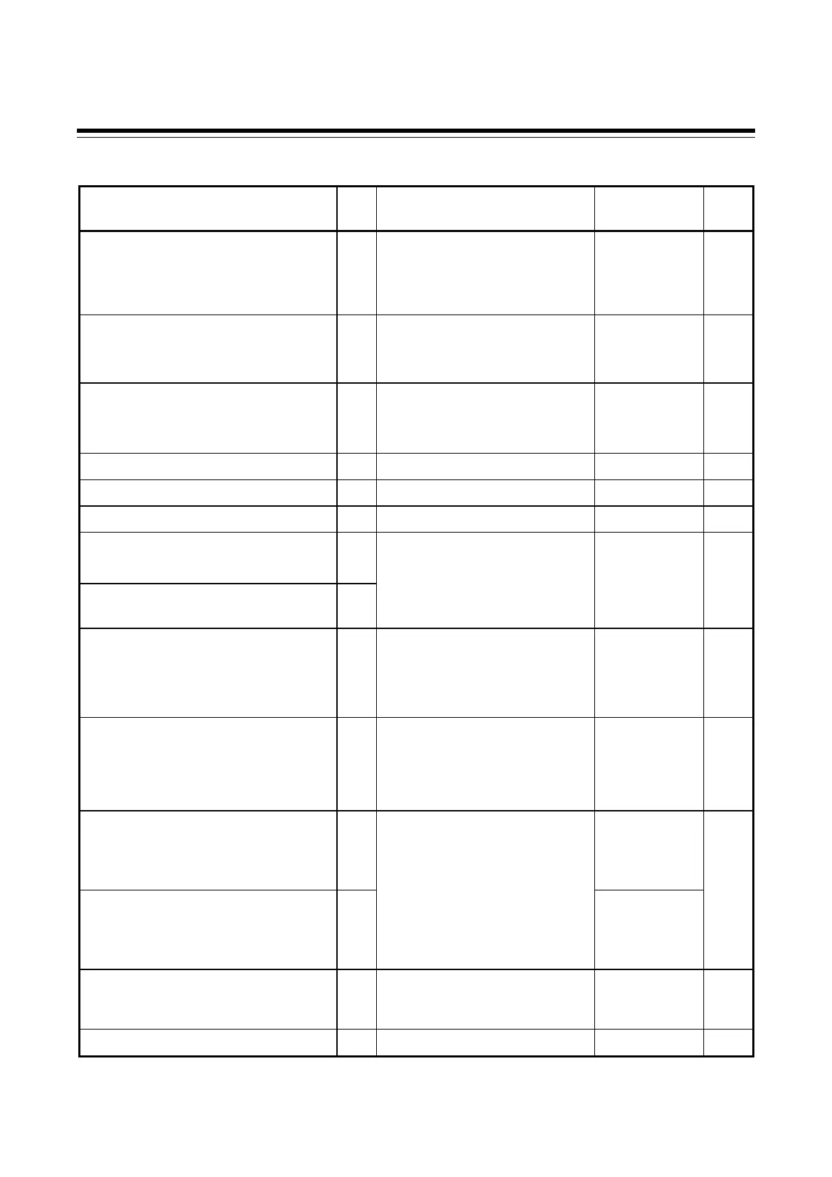
3. COMMUNICATION INITIAL IDENTIFIER
IMCB04-E10
25
ID: Identifier (RO: Read only R/W: Read/write)
Name ID Data range Factory
set value
R/W
Control action type selection [SL6] CA 0 to 15
3
To vary
depending on
the
specification
R/W
Energized/de-energized alarm
selection, special specification
selection 1 [SL7]
Z1 0 to 15
4
0
R/W
Special specification selection 2 [SL8] Z2 0: Z-185 specification not
provided
2: Z-185 specification provided
0
R/W
Special specification selection 3 [SL9] Z3 0 to 14
5
0
R/W
Option selection [SL10] DH 0 to 15
6
0
R/W
SV alarm type selection [SL11] XC 0 to 15
7
0
R/W
Setting limiter (high limit) [SLH] XV See input range table
(P.17 to 19)
To vary
depending on
R/W
Setting limiter (low limit) [SLL] XW
the
specification
Setting the position of decimal point
[PGdP]
XU 0: No decimal place
1: One decimal place
2: Two decimal places
3: Three decimal places
1
R/W
Differential gap setting of ON/OFF
action [oH]
MH For TC/RTD inputs:
0 (0.0) to 100 (100.0) °C [°F]
For voltage/current inputs:
0.0 to 10.0 % of span
TC, RTD input:
2 or 2.0
Voltage/current
input: 0.2
R/W
Differential gap setting of alarm 1
(ALM1) [AH1]
HA
TC, RTD input:
2 or 2.0
Voltage/current
input: 0.2
R/W
Differential gap setting of alarm 2
(ALM2) [AH2]
HB
For TC/RTD inputs:
0 (0.0) to 100 (100.0) °C [°F]
For voltage/current inputs:
0.0 to 10.0 % of span
TC, RTD input:
2 or 2.0
Voltage/current
input: 0.2
CT ratio setting [CTr] XR 0 to 9999
CTL-6-P-N: 800
CTL-12-S56-
10L-N: 1000
R/W
Digital filter setting [dF] F1 0 to 100 seconds
0
R/W
Continued on the next page.

 Loading...


