2. SETTING
IMCB04-E10
7
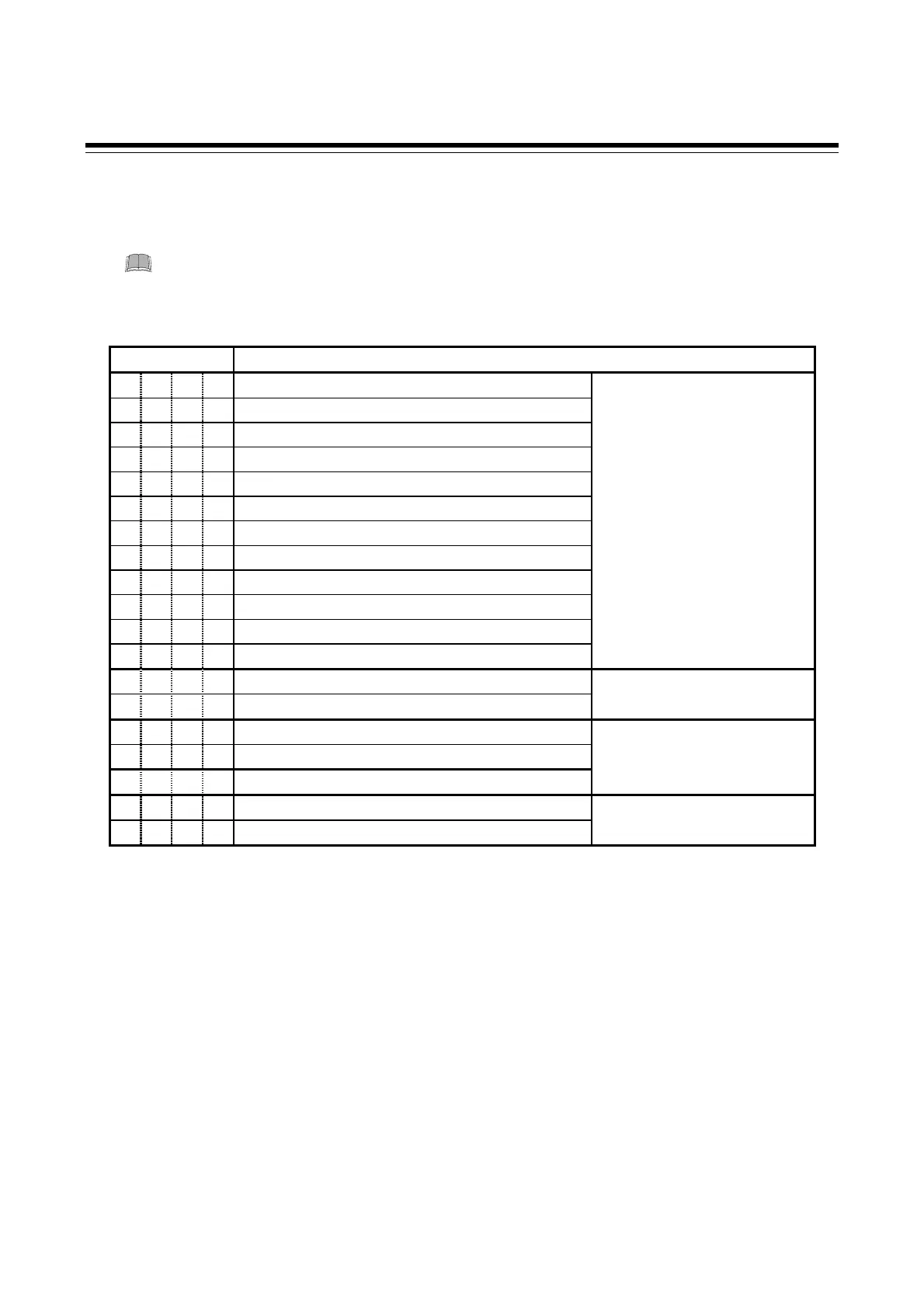
2.3 List of Parameters in Initialize Code 0 (Cod = 0)
(1) SL1 (Input type selection)
When any parameter setting is changed in the Initialization Mode, check all parameter
set values in SV Setting Mode and Parameter Setting Mode.
Factory set value varies depending on the input type.
Set value Input type
0 0 0 0 K
0 0 0 1 J
0 0 1 0 L
0 0 1 1 E
0 1 0 0 N
0 1 1 1 R
1 0 0 0 S
1 0 0 1 B
2
1 0 1 0 W5Re/W26Re
2
1 0 1 1 PL II
0 1 0 1 T
0 1 1 0 U
3
TC input
1
1 1 0 0 Pt100 Ω (JIS/IEC)
1 1 0 1 JPt100 Ω (JIS)
RTD input
1
1 1 1 0 0 to 5 V DC
1 1 1 0 0 to 10 V DC
4
Voltage input
1
1 1 1 1 1 to 5 V DC
1 1 1 0 0 to 20 mA DC
1 1 1 1 4 to 20 mA DC
Current input
1, 5
1
Any input change in TC and RTD Group is possible. Any input change in voltage and current Group
except for 0 to 10 V DC input is possible. No input change between TC and RTD Group and voltage
and current Group is possible.
2
W5Re/W26Re and B are not available with Z-1021 specification (Modbus communication).
3
Type U input is not available with Z-1038 specification.
If set value is set to “0110” with Z-1038 specification, becomes input type K (0.0 to 800.0 °C).
4
The input type of Z-1010 specification is fixed to 0 to 10 V DC due to the hardware difference.
5
For the current input specification, a resistor of 250 Ω must be connected between the input
terminals.

 Loading...


