5)
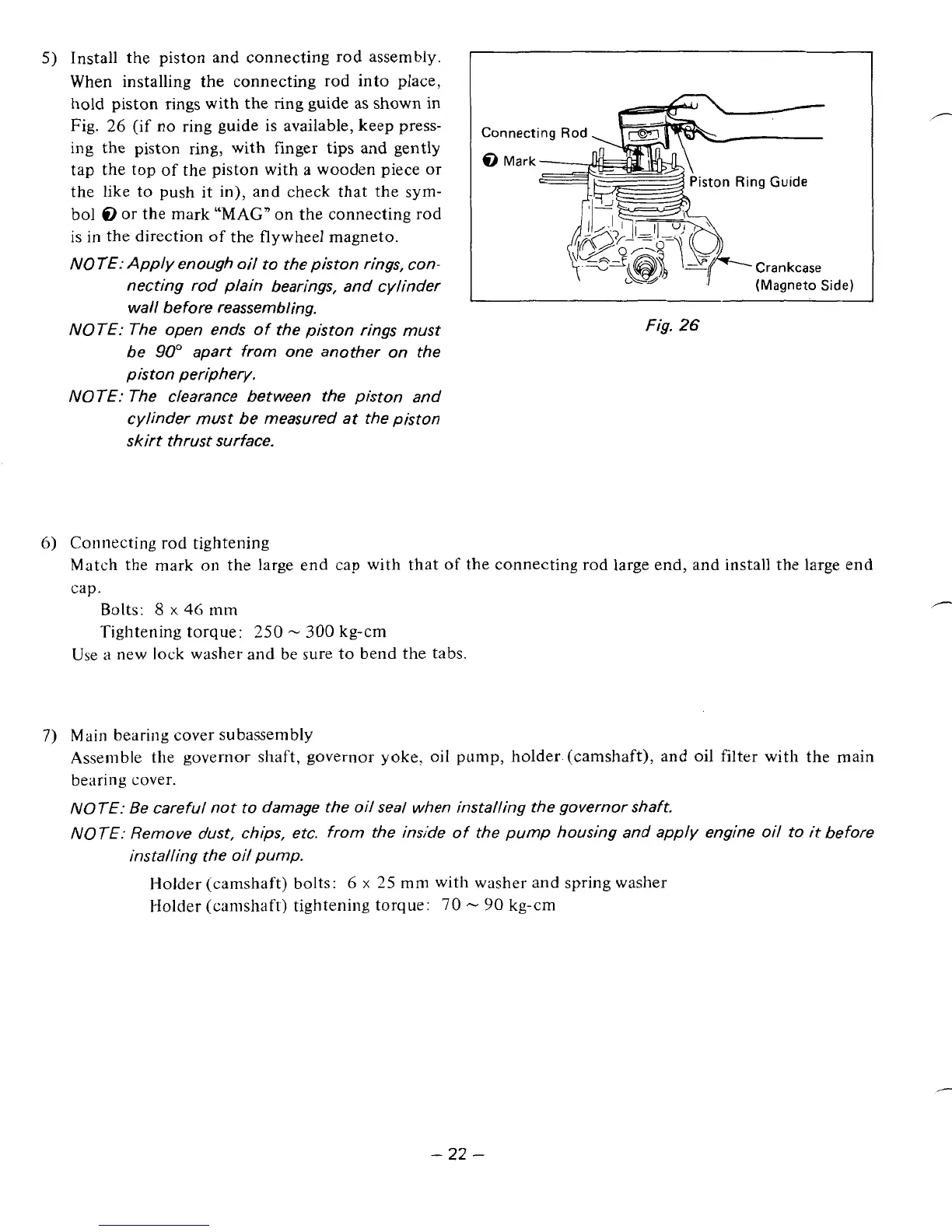
Install the piston and connecting rod assembly.
When installing the connecting rod into place,
hold piston
rings
with the ring guide as shown
in
Fig.
26
(if
no
ring guide
is
available, keep press-
ing the piston
ring,
with finger tips and gently
tap the top of the piston with a wooden piece
or
the like to push it in), and check that the
sym-
bol
8
or
the mark
“MAG”
on
the connecting rod
is in the direction
of
the flywheel magneto.
NOTE: Apply enough oil to the piston rings, con-
necting rod plain bearings, and cylinder
wall before reassembling.
NOTE: The open ends of the piston rings must
be
90”
apart from one another on the
piston periphery.
NOTE: The clearance between the piston and
cylinder must be measured at the piston
skirt thrust surface.
iston
Ring Guide
(Magneto Side)
Fig.
26
6)
Connecting
rod
tightening
Match the mark on the large end cap with that
of
the connecting rod large end, and install the large end
cap.
Bolts:
8
x
46
mm
Tightening torque:
250
-
300
kg-cm
Use
a
new lock washer and be sure to bend the tabs.
7)
Main
bearing cover subassembly
Assemble the governor shaft, governor yoke,
oil
pump, holder (camshaft), and oil filter with the main
bearing cover.
NOTE: Be careful not to damage the oil
seal
when installing the governor shaft.
NOTE: Remove dust, chips, etc. from the inside
of
the pump housing and apply engine oil to
it
before
installing the oil pump.
Holder (camshaft) bolts:
6
x
25
mm
with washer and spring washer
Holder (camshaft) tightening torque:
70
-
90
kg-cm
-
22
-