5-3-3 DC OUTPUT
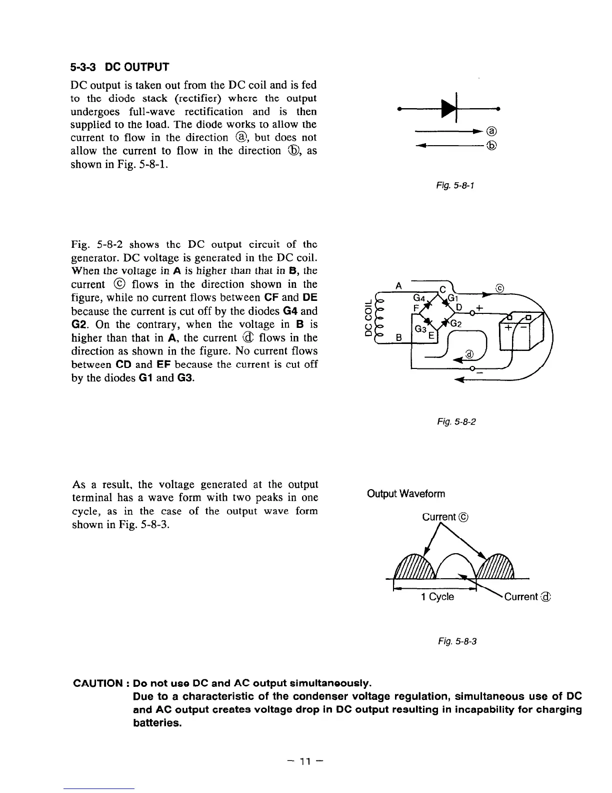
DC output is taken out from the DC coil and is fed
to the diode stack (rectifier) where the output
undergoes full-wave rectification and is then
supplied to the load. The diode works to allow the
current to flow in the direction 83, but does not
allow the current to flow in the direction 8, as
shown in Fig. 5-8-l.
Fig. 5-8-7
Fig. 5-8-2 shows the DC output circuit of the
generator. DC voltage is generated in the DC coil.
When the voltage in
A
is higher than that in 6, the
current @ flows in the direction shown in the
A
figure, while no current flows between CF and
DE
because the current is cut off by the diodes G4 and
G2. On the contrary, when the voltage in
B
is
higher than that in
A,
the current (2 flows in the
x
B
direction as shown in the figure. No current flows
between
CD
and
EF
because the current is cut off
by the diodes
Gl
and G3.
Fig. 5-8-2
As a result, the voltage generated at the output
terminal has a wave form with two peaks in one
cycle, as in the case of the output wave form
shown in Fig. 5-B-3.
Output Waveform
Fig. 5-8-3
CAUTION : Do not use DC and AC output simultaneously.
Due to a characteristic of the condenser voltage regulation, simultaneous use of DC
and AC output creates voltage drop in DC output resulting in incapability for charging
batteries.
- 11 -
 Loading...


